Loop Rule
Claimed by Sahil Arora (Fall 2016)
The Loop Rule, also known as Kirchhoff's Second Law, is a fundamental principle of electric circuits which states that the sum of potential differences around a closed circuit is equal to zero. More simply, when you travel around an entire circuit loop, you will return to the starting voltage. Note that is only true when the magnetic field is neither fluctuating nor time varying. If a changing magnetic field links the closed loop, then the principle of energy conservation does not apply to the electric field, causing the Loop Rule to be inaccurate in this scenario.
The Energy Principle and Loop Rule
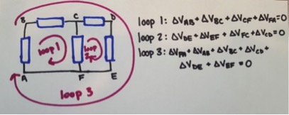
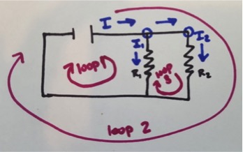
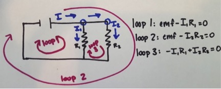
The loop rule simply states that in any round trip path in a circuit, Electric Potential equals zero. Keep in mind that this applies through ANY round trip path; there can be multiple round trip paths through more complex circuits. This principle deals with the conservation of energy within a circuit. Loop Rule and Node Rule are the two fundamental principles of electric circuits and are used to determine the behaviors of electric circuits. This principle is often used to solve for resistance or current passing through of light bulbs and other resistors, as well as the capacitance or charge of capacitors in a circuit.
A Mathematical Model
A mathematical representation is:
- [math]\displaystyle{ \sum_{i=1}^n {V}_{i} = 0 }[/math]
where n is the number of voltages being measured in the loop, as well as
- [math]\displaystyle{ \Delta {V}_{1} + \Delta {V}_{2} + \space.... = 0 }[/math]
along any closed path in a circuit.
A Visual Model
To figure out the sign of the voltages, act as an observer walking along the path. Start at the negative end of the emf and continue walking along the path. The emf will be positive in the loop rule because you are moving from low to high voltage. Once you reach a resistor or capacitor, this will be negative in the loop rule equation because it is high to low voltage. Continue along the path until you return to the starting position.
Examples
For further instruction, check out these YouTube videos [1] [2]
Simple
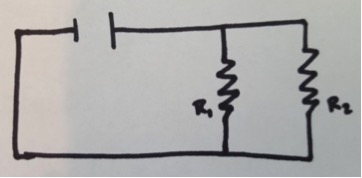
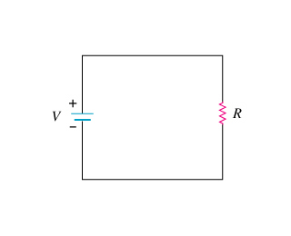
The circuit shown above consists of a single battery and a single resistor. The resistance of the wires is negligible for this problem.
Problem:
If the [math]\displaystyle{ emf }[/math] is 5 V and the resistance of the resistor is 10 ohms, what is the current passing through the resistor.
Solution:
Although we can solve this using the V = IR equation for the whole loop, lets examine this problem using the loop rule equation.
The loop rule equation would be [math]\displaystyle{ {V}_{battery} - {V}_{resistor} = 0 }[/math]
Since we know the [math]\displaystyle{ emf }[/math] of the battery we just need to find the potential difference through the resistor. For this we can use the equation of V = IR.
Thus we now have an loop rule equation of [math]\displaystyle{ emf - IR = 0 }[/math] From here it is a relatively simple process to find the current. We can rewrite the loop rule equation as [math]\displaystyle{ emf = IR }[/math] and then plug in 5 for the emf and 10 for the resistance, leaving us with I = .5 amperes.
Middling
Problem:
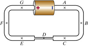
The circuit shown above consists of a single battery, whose [math]\displaystyle{ emf }[/math] is 1.3 V, and three wires made of the same material, but having different cross-sectional areas. Let the length of the thin wires be [math]\displaystyle{ {L}_{thick} }[/math] and the length of the thin wire be [math]\displaystyle{ {L}_{thin} }[/math] Find a loop rule equation that starts at the negative end of the battery and goes counterclockwise through the circuit.
Solution:
When beginning this problem, you must notice that the difference in cross-sectional areas affects the electric field in each wire. Because of this we will denote the electric field at D. as [math]\displaystyle{ {E}_{D} }[/math] and the electric field everywhere else as [math]\displaystyle{ {E}_{A} }[/math]. To begin we will go around the circuit clockwise and add up each component. First, we know that the [math]\displaystyle{ emf }[/math] of the battery is 1.3 V. Then, we will add up the potential voltage of each of the wires.
Remember that the electric potential of a wire is equal to the electric field * length of the wire. From his we can now find the potential difference of each section of the wires. The electric potential of location A - C is [math]\displaystyle{ {E}_{A} * {L}_{thick} }[/math]. This is the same for the electric potential of location E - G of the wire. For the thin section of the wire, the electric potential is [math]\displaystyle{ {E}_{D} * {L}_{thin} }[/math]. From here we just go around the circuit counterclockwise and add each potential difference to the loop rule equation.
Thus we can find that a loop rule equation is: [math]\displaystyle{ emf - 2 ({E}_{A} * {L}_{thick}) - {E}_{D} * {L}_{thin} = 0 }[/math]
This can also be rewritten as: [math]\displaystyle{ emf = 2 ({E}_{A} * {L}_{thick}) + {E}_{D} * {L}_{thin} = 0 }[/math]
Difficult
Problem:
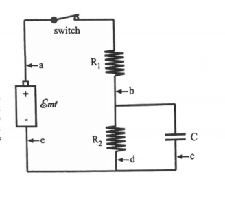
For the circuit above, imagine a situation where the switch has been closed for a long time. Calculate the current at a,b,c,d,e and charge Q of the capacitor. Answer these using [math]\displaystyle{ emf, {R}_{1}, {R}_{2}, and \space C }[/math]
Solution:
First, write loop rule equations for each of the possible loops in the circuit. There are 3 loop equations that are possible.
[math]\displaystyle{ emf - {I}_{1}{R}_{1} - {I}_{2}{R}_{2} = 0 }[/math]
[math]\displaystyle{ emf - {I}_{1}{R}_{1} - Q/C = 0 }[/math]
[math]\displaystyle{ {I}_{2}{R}_{2} - Q/C = 0 }[/math]
From here, we can then solve for the current passing through a,b,d and e. We also know that the current passing through these points must be the same so [math]\displaystyle{ {I}_{1} = {I}_{2} }[/math]
[math]\displaystyle{ emf - {I}_{1}{R}_{1} - {I}_{1}{R}_{2} = 0 }[/math]
[math]\displaystyle{ emf = {I}_{1}({R}_{1} + {R}_{2}) = 0 }[/math]
[math]\displaystyle{ emf/({R}_{1} + {R}_{2}) = {I}_{1} }[/math]
So the current at a,b,d,e = [math]\displaystyle{ emf/({R}_{1} + {R}_{2}) }[/math]
You must also know that once a capacitor is charging for a long time, current no longer flows through the capacitor. We can then easily solve for c because since current is no longer flowing through the capacitor, the current at c = 0.
Lastly, we will use the loop rule equation of [math]\displaystyle{ {I}_{2}{R}_{2} - Q/C = 0 }[/math] to solve for Q.
[math]\displaystyle{ {I}_{2}{R}_{2} = Q/C }[/math]
[math]\displaystyle{ C*({I}_{2}{R}_{2}) = Q }[/math] Since [math]\displaystyle{ {I}_{1} = {I}_{2} }[/math]
[math]\displaystyle{ C*({I}_{1}{R}_{2}) = Q }[/math] Lastly, we will plug in what we found {I}_{1} equals from before.
[math]\displaystyle{ C* (emf/({R}_{1} + {R}_{2})){R}_{2}) = Q }[/math]
Lastly, Q = [math]\displaystyle{ C* (emf/({R}_{1} + {R}_{2})){R}_{2} }[/math] and we have now solved the problem.
Answers:
Current at a,b,d,e = [math]\displaystyle{ emf/({R}_{1} + {R}_{2}) }[/math]
Current at c = 0
Q = [math]\displaystyle{ C* (emf/({R}_{1} + {R}_{2})){R}_{2} }[/math]
History
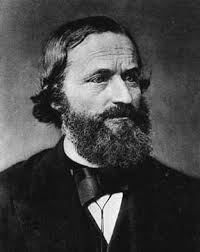
The Loop Rule is formally known as the Kirchhoff Voltage Laws, named after Gustav Kirchhoff, the scientist who discovered and defined this fundamental concept of electric circuits. He discovered this during his time as a student at Albertus University of Königsberg in 1845. Kirchoff went on to explore the topics of spectroscopy and black body radiation after his graduation from Albertus. Nowadays, it is used very often in electrical engineering.
Connectedness
Because I am a Computer Science majors, while circuits are not directly connected to programming, computers and other electronics are made of different circuits. Loop Rule is used in the electrical engineering that is required to create the circuits for the computers I use to program.
One interesting note about Loop Rule is that is does not apply universally to all circuits. In particular, AC (alternating current) circuits, have a fluctuating electric charge that changes direction. This causes the electric potential of a round trip path around the circuit to no longer be zero. However, DC (direct current) circuits still follow the loop rule.
See also
Other Circuit Concepts you can check out :
More Information and External links
Kirchoff's Circuit Laws - Wikipedia
Loop Rule - Boundless.com Textbook
Loop Rule - Doc Physics Video Lecture
References
- Dr. Nicholas Darnton's lecture notes
- https://en.wikipedia.org/wiki/Kirchhoff%27s_circuit_laws#Kirchhoff.27s_voltage_law
- Chabay, Ruth W. Matter and Interactions: Electric and Magnetic Interactions. John Wiley, 2015. Print.
- http://www.ux1.eiu.edu/~cfadd/1360/28DC/Loop.html
- Mason, J. (Producer). (2012). How to Solve a Kirchhoff's Rules Problem [Motion picture]. United States of America: YouTube.
- Anderson, P. (2015, March 09). Kirchoff's Loop Rule. Retrieved April 16, 2016, from https://www.youtube.com/watch?v=paDs-Hnmklo
Claimed by Bmock7

