Two Dimensional Harmonic Motion
The one dimensional spring-mass system provided a good example of harmonic motion. Adding dimensions complicates the picture, but also demonstrates how the same principles developed there are generally applicable in more realistic situations. The pendulum is approximately a simple harmonic system, but this approximation is weaker when the amplitude of the oscillation is greater. The swinging spring is distinctly not simple harmonic oscillator, but it still has harmonic features, and approaches a pendulum under extreme conditions, as will be analyzed in one of the examples.
Main Idea
In addition to the processes of damping and driving which were considered in Iterative Prediction of Spring-Mass System, other complications exist which provide variations on harmonic motion. This article considers two types of two dimensional cases: the pendulum, which is approximately harmonic motion, and the swinging spring which is related to but substantially more complex than harmonic motion.
Mathematical Method
Two examples of harmonic motion in multiple dimensions will be considered: the pendulum and the swinging spring-mass system. In both cases, there exists the force of gravity pointing downwards, and another force pointed towards the center of rotation. We will not consider the analytic methods of solving these problems (for the first steps in doing so, see Centripetal Force and Curving Motion). Instead, we will define the forces present, and then implement an iterative model.
The Pendulum
The simpler of the two cases is the pendulum. In this scenario, we neglect air resistance, and have a mass attached to a rod of negligible mass with a fixed length [math]\displaystyle{ R }[/math]. We will treat the pivot point as the origin of the system, so that no coordinate conversions are necessary when computing angles. The force from the rod is a constraint force, meaning that it acts exactly to ensure the mass always stays on the arc of equal distance to the pivot point. For this to occur, it is necessary that the force directed towards the center always be the centripetal force necessary to maintain that arc, which is defined as a force pointed towards the pivot point with a magnitude
[math]\displaystyle{ |F_c| = \frac{v^2}{r} }[/math]
The situation is complicated by the fact that gravity is present. Gravity is defined as always:
[math]\displaystyle{ \vec{F}_g = -mg \hat{y} }[/math]
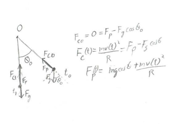
Now, let us imagine the situation, illustrated in this figure:
We release the pendulum from height [math]\displaystyle{ h }[/math] at an angle [math]\displaystyle{ \theta_0 }[/math]. At this point, its velocity will be zero, so the centripetal force must equal zero. However, gravity must still be present, so there must be some pendulum force to cancel gravity's radial component. From this we know its magnitude must be
[math]\displaystyle{ F_p (t) = mg\cos(\theta)+\frac{mv^2}{R} }[/math]
Now all we need to do is use trigonometry to determine the forces in the x and y direction:
[math]\displaystyle{ F_x = - F_p\sin(\theta) = -(mg\cos(\theta)\sin(\theta) + \frac{mv^2}{R}) }[/math]
Note the negative direction, because of how we have oriented our angles. Next, we have the slightly more complicated expression
[math]\displaystyle{ F_y = F_p\cos(\theta)-mg = mg\cos^2(\theta) + \frac{mv^2}{R}\cos(\theta) - mg }[/math]
Plugging these in to a numerical simulator will allow us to arrive at our desired answer.
Now, some interesting features of pendula may be noted. They will not be derived, but you are encouraged (see: the examples) to explore this behavior using a simulation. The most important feature can be noted by looking at the equations for force: each of the terms on the right has a mass term present, and on the left force is linearly dependent on mass. This means that the mass will actually fall out of the equations of motion: the motion will be determined solely by the initial conditions, the length of the pendulum, and the strength of gravity. You will see that the pendulum executes oscillatory motion, with an angular frequency
[math]\displaystyle{ \omega = \sqrt{\frac{g}{R}} }[/math]
Furthermore, for sufficiently small angles, this frequency is independent of the starting angle. The caveat about smaller angles is because, even in the absence of air resistance, is an approximation to say that the pendulum is a simple harmonic oscillator (specifically, it involves the approximation [math]\displaystyle{ \sin(\theta) = \theta }[/math]), but this approximation is very strong for smaller angles, so it's generally good enough.
The Swinging Spring
This problems is both more and less complicated than the one above. On the one hand, the force from the spring is not a centripetal restraining force, and so it will be more complicated to write out. On the other hand, it is conceptually easier to work with, because all we have to do is consider the two base forces and implement them, rather than thinking about the nature of the net force. First, gravity will stay the same as above, which should not be surprising. Next, we need to implement the spring force, as described in Simple Harmonic Motion and Iterative Prediction of Spring-Mass System. The Hookeian spring is governed by the equation
[math]\displaystyle{ \vec{F}_s = -k(\vec{r}-\vec{r}_0) }[/math]
This means that we define the rest length of the spring, then compute the current deviation of the spring from that rest length in order to determine the force. The force will always be directed along the axis of the spring, which in this cases means radially from the pivot point, as above (we will be assuming the spring stays straight - real springs will also have some curvature, but this can get very complicated). Given this, when the spring is at some angle [math]\displaystyle{ \theta }[/math], defined as above, we can determine our forces to be:
[math]\displaystyle{ \vec{F}_x =\vec{F}_s \cdot \hat{x} = k (\vec{r}-r_0\hat{r})\cdot\hat{x} }[/math]
This notation may be confusing, since it uses the inner product notation. This is meant to indicate that not only is the magnitude of [math]\displaystyle{ \vec{F}_s }[/math] important, but so is its sign. In the code, this is easy to implement, but notationally it is more difficult. One could explicitly write the equation out with trigonometric functions as
[math]\displaystyle{ \vec{F}_x = -|k (\vec{r}-r_0\hat{r})|(Sign(\vec{r}-r_0\hat{r}))\sin(\theta)\hat{x} }[/math]
but as you can see, it starts to get very clumsy, so instead this page will stick with vector notation. The coefficient sign is positive because we have one negative from the definition of a Hookeian spring, and another from our coordinate system (see above). Notice as well, the definition of the equilibrium point was made explicit, as we define it as being the point along the radial vector from the pivot to the object, with distance from the pivot of [math]\displaystyle{ r_0 }[/math]. The force in the y direction is slightly more complicated, but follow similarly:
[math]\displaystyle{ \vec{F}_y = \vec{F}_s\cdot\hat{y} -mg\hat{y} = -k(\vec{r}-r_0\hat{r})\cdot\hat{y} - mg\hat{y} }[/math]
Computational Method
The Pendulum
Given the forces we derived above, it is fairly straightforward to plug these into a numerical simulator along with a set of initial conditions. This does it using the numpy code described in Predicting Change in multiple dimensions.
The Swinging Spring
Given the forces we derived above, it is fairly straightforward to plug these into a numerical simulator along with a set of initial conditions. This does it using the numpy code described in Predicting Change in multiple dimensions.
Examples
Simple Example
Consider a pendulum consisting of a massless rod of length [math]\displaystyle{ 2.45 \; m }[/math] attached to an object of mass [math]\displaystyle{ 4 \; kg }[/math]. Assume that the acceleration due to gravity is equal to [math]\displaystyle{ 9.8 \; \frac{m}{s^2} }[/math], the initial angle is fairly small, and no air resistance is present. Compute the period of this pendulum. Confirm your result using a simulator
As long as we use the correct initial information and equations, this is a very straightforward problem. Remember that we have the formula for angular frequency
[math]\displaystyle{ \omega = \sqrt{\frac{g}{r}} }[/math]
Note that this formula does not include the mass of the object (although the assumption that the rod is important); the information about the mass was therefore a red herring. It is very straightforward then to compute that [math]\displaystyle{ \omega = 2 \; Hz }[/math]. Now, from this we can compute the period [math]\displaystyle{ T }[/math] using the relations
[math]\displaystyle{ \omega = 2\pi f }[/math]
[math]\displaystyle{ T = \frac{1}{f} }[/math]
where [math]\displaystyle{ f }[/math] is the normal frequency. Then we can substitute in to find that
[math]\displaystyle{ T = \frac{2 \pi}{\omega} = \frac{2 \pi }{2 \; Hz } = \pi \; s }[/math]
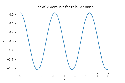
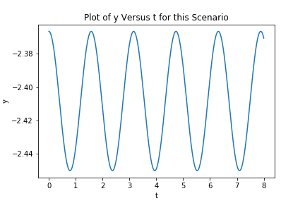
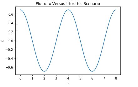
Now, let's confirm this with the simulator:
We can see that the period in x is indeed [math]\displaystyle{ \pi \; s }[/math]. The period in y is equal to [math]\displaystyle{ \frac{\pi}{2} \; s }[/math], which makes sense if one visualizes the pendulum: it will reach the same height both at its farthest left point and its farthest right point, so it will reach that height twice as often as it reaches its starting point. When we speak of the pendulum's period, however, we mean specifically the time it takes to return to its initial position, so the period in x is what we want.
Middling Example
Consider a massless spring of relaxed length 1 m with spring constant 120 N/m attached to the ceiling. If a 2 kg mass is released with an initial velocity of <1.5, 0.5, -0.5> m/s at an initial position of <-1, 1, 1> m, what is the velocity of the block after 0.005 seconds? Consider the point of attachment on the spring to the ceiling to be the origin. Only one iteration is necessary.
First, we calculate the initial momentum.
[math]\displaystyle{ {\vec{p}_{i}} = {{m}\cdot\vec{v}_{i}} }[/math]
[math]\displaystyle{ {\vec{p}_{i}} = {2kg\cdot{\lt 1.5, 0.5, -0.5\gt \; m/s}} = \lt 3, 1, -1\gt \;Ns }[/math]
As always, we have the force of gravity
[math]\displaystyle{ {\vec{F}_{grav}} = {m}{\lt 0, -g, 0\gt } }[/math]
[math]\displaystyle{ {\vec{F}_{grav}} = {2kg}\cdot{\lt 0, -9.8, 0\gt \; m/s^2} = {\lt 0, -19.6, 0\gt N} }[/math]
Now, a more complicated matter is the force of the spring
[math]\displaystyle{ \vec{F}_{spring} = -k(\vec{r}-\vec{r}_{0}) }[/math]
Using vector notation allows us to use this as a shortcut: Hooke's law is linear, so we can evaluate it separately for each components, as long as we get [math]\displaystyle{ \vec{r}_0 }[/math] right. To do this, we unit vector of the initial position:
[math]\displaystyle{ \hat{r} = \frac{\vec{r}}{|\vec{r}|} }[/math]
The magnitude of [math]\displaystyle{ r }[/math] is simply
[math]\displaystyle{ |\vec{r}| = \sqrt{(-1 \; m)^2 + (1 \; m)^2 + (1 \; m)^2} = \sqrt{3} \; m }[/math]
So then the unit vector will be
[math]\displaystyle{ \frac{\lt -1,1,1\gt \; m}{\sqrt{3} \; m} = \lt -\frac{\sqrt{3}}{3},\frac{\sqrt{3}}{3},\frac{\sqrt{3}}{3}\gt }[/math]
Now, we have
[math]\displaystyle{ \vec{r}_0 = r_0 \hat{r} = (1\; m) \lt -\frac{\sqrt{3}}{3},\frac{\sqrt{3}}{3},\frac{\sqrt{3}}{3}\gt = \lt -\frac{\sqrt{3}}{3},\frac{\sqrt{3}}{3},\frac{\sqrt{3}}{3}\gt \; m }[/math]
And so the force from the spring will be
[math]\displaystyle{ \vec{F}_s = -(120)(\lt -1,1,1\gt -\lt \lt -\frac{\sqrt{3}}{3},\frac{\sqrt{3}}{3},\frac{\sqrt{3}}{3}\gt ) \; N = (120-40\sqrt{3})\lt 1,-1,-1\gt \; N }[/math]
Next, we calculate the net force by summing the two forces.
[math]\displaystyle{ {\vec{F}_{net}} = {\vec{F}_{grav} +{\vec{F}_{spring}}} }[/math]
[math]\displaystyle{ {\vec{F}_{net}} = {\lt 0, -13.72, 0\gt N} +{\lt 12.83316, -29.94405, -8.55544\gt N} = {\lt 12.83316, -16.22405, -8.55544\gt N} }[/math]
Step 5: Update Momentum
Using the momentum update formula, calculate the momentum of the mass at the end of the given time step.
[math]\displaystyle{ {\vec{p}_{f} = \vec{p}_{i} + \vec{F}_{net}{Δt}} }[/math]
[math]\displaystyle{ {\vec{p}_{f} = {\lt 1.68, 1.12, -0.28\gt Ns} + {\lt 12.83316, -16.22405, -8.55544\gt N}\cdot{0.005s} = { Ns}} }[/math]
[math]\displaystyle{ {\vec{p}_{f} = {\lt 1.7442, 1.0389 ,-0.3611\gt Ns}} }[/math]
Step 4: Calculate Velocity
[math]\displaystyle{ {\vec{v}_{f}} = \frac{\vec{p}_{f}}{m} }[/math]
[math]\displaystyle{ {\vec{v}_{f}} =\frac{\lt 1.7442, 1.0389 ,-0.3611\gt Ns}{1.4kg} = {\lt 1.2458, 0.7421, -0.2579\gt m/s} }[/math]
Step 5: State Answer
After 0.005 seconds, the mass is moving with velocity <1.25, 0.74, -0.26> m/s
Difficult Example
Let's analyze some of the behavior of the swinging spring system using a simulator. We will have to rely on the simulator because the system is chaotic, a topic which is explored more in Determinism. Instead of considering suck behavior here, we are going to focus on a few edge cases where we can predict the behavior.
- First, to test the simplest case, set the spring coefficient equal to zero. The set rest length, initial position, and initial velocity to whatever you want. Predict the behavior before hand, and then run the simulation. What you see should be very familiar (hint: set the duration fairly low, the behavior is obvious even on short time scales, so there's no reason to have it run for a long time). Briefly explain why this occurred.
- Now set the spring with a reasonable spring coefficient (say [math]\displaystyle{ 4.9 \; \frac{N}{m} }[/math] for example). Set its initial conditions such that it has no initial velocity, and its initial position is hanging straight down, starting at its rest length. Observe the behavior, and explain what you see. Did anything surprise you?
- Finally, set the spring coefficient very high (the solution has it set to [math]\displaystyle{ 11,000 \; \frac{N}{m} }[/math]). Set the system at a small angle and let it run. What behavior do you expect to see from this? It is useful to think about the physical system, and what it will be similar to. It is important to note that what we are doing will tax the numerical stability of the program, so it is strongly advised that you do this at a very small initial angle, and use very short time steps, or else the system may go crazy. You'll want to have a reasonable amount of duration to view, so this simulation is likely to take a very long time, such that you should probably do something else while you wait for it to finish. You should also make plots with respect not only to the position in x and y, but also the forces and velocities
- Once you think through the implications of setting [math]\displaystyle{ k = 0 }[/math], the answer should be fairly obvious: if [math]\displaystyle{ k = 0 }[/math], [math]\displaystyle{ \vec{F}_s = 0 }[/math], in which case the only force the object feels is that due to gravity. When an object feels force only due to gravity, it is a projectile, and the behavior of the simulation bears this out.
- This is a more interesting problem, but again it should be familiar, since if you have worked through Iterative Prediction of Spring-Mass System you have seen it before. When we deprive it of initial forces or velocities in the x direction, it becomes a one dimensional problem, namely of an object on a spring oscillating due to the force of gravity. Although it was set at its rest length, the actual equilibrium point is below this position (you can compute it by finding the length at which the spring force is equal to the force of gravity). Therefore, by setting it here, we have produced a simple harmonic oscillator.
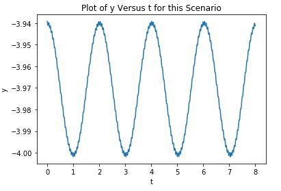
- This final case is an interesting thought experiment that relies on understanding what [math]\displaystyle{ k }[/math] really is. Simply put, it is the resistance of the spring to deformation, so by setting it very high, we have produced a spring that essentially isn't a spring at all, but is instead a mass, inflexible rod, which means that it is essentially just a pendulum. Performing the simulation very carefully bears this result out.
As you can see, the position in y is very shaky. If you did not already, look at the force a velocity and force graphs: they will be extremely shaky. This is a visual example of the numerical instability of this problem, and is the reason we needed to keep the time steps so small, lest the system "shake" itself out of the stable trajectory, at which point it would very quickly go off the rails. With careful control, however, we were able to get a physically intuitive solution and produce an alternative (extremely inefficient) piece of pendulum code.
Connectedness
[A student should fill this out]
History
The scientific history of the pendulum begins, like so many concepts in classical mechanics, with Galileo Galilei, who noted the constant rate of a pendulums motion at the turn of the 17th century[1]. This early use of physics turned out to have a great deal of practical use, as Christiaan Huygens developed the pendulum clock in the mid 17th century[2]. Pendulum clocks were substantially more accurate than their precursors, although by modern standards they still had a long ways to go (Huygens pendulum clock would drift about 15 seconds every day). Huygens also made an interesting discovery: two pendula placed on the same base would eventually synchronize. The question of why is still not completely solved, but the supposition that it was due to minute vibrations in the connecting base was verified in 2000 by Georgia Tech faculty. [3]
See Also
- Predicting Change in multiple dimensions
- Simple Harmonic Motion
- Determinism
- Iterative Prediction of Spring-Mass System
External Links
- The pendulum by hyperphysics
- The swinging spring in greater detail
- Synchronization in the related case of metronomes
Further Reading
- Matter and Interactions, 4th Edition
