Series Circuits
Jump to navigation
Jump to search
CLAIMED by Rama Sambatur spring 2018
The Main Idea
- A circuit is an electrical apparatus that is borne out of an electric field mobilizing charges in a conductor and creating a gradient of energy that leads the system to want to reach an equilibrium. However, in a circuit, the applied electric field never reaches zero; hence, the motion of the mobile charges flows for a long time around the conducting circuit through a "Current". This notion depicts a flow of electrons that exists in a "Steady-State" in which the drift velocities of the electrons do not change with time and in which there is no build up of excess charge anywhere along the circuit.
- A series circuit is the most simple type of electrical circuit in which components (i.e. - Batteries, Resistors, Capacitors, Solenoids, etc...) are placed in succession of one another. A circuit in series only has one loop that can be drawn throughout. The electrical connection is not branched in any way and any disruption of the circuit causes the entire circuit to lose current.
Example of a Series Circuit with multiple components
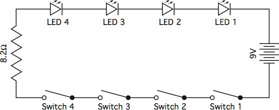

- One can visualize this circuit as simply a closed loop. simple circuits often contain multiple components of differing resistances and functions which can be solved for using the loop rule. These components include: resistors, switches, capacitors, inductors, and of course, batteries.
The Loop Rule
- The non-equilibrium steady-state nature of a series circuit allows for relatively simple calculations needed to define the quantities of components around a circuit.
- When attempting to solve for said quantities along a series circuit, simply follow "The Loop Rule", derived from Kirchhoff's laws as well as Ohm's law that allow for electric potential, current, or resistance(s) to be solved for.
- To begin, draw a loop beginning from the positive terminal of the battery and trace it in a clockwise/counter-clockwise "loop" along the single path to end at the negative terminal.
- More complex circuits with parallel and series circuit aspects may have multiple loops and may consequently require more relations, however, the loop rule will still hold true in smaller loops of the larger circuit.
- Since the battery/alternate power source is the driver of the electric field and the current, all the components along the circuit detract from the potential difference generated by the battery to satisfy the Law of Conservation of energy. In other words, the voltage supplied by the battery equals the cumulative potential difference across any and all components along the series circuit. While the voltage/potential difference of the battery is generally given, the potential differences across the components each have to be solved for with respect to their own properties.

- The sum of the current at each resistor multiplied by its resistance must be equal to the electric potential of the battery. In other words, sum of the current going into the circuit must be equal to sum of the current leaving. The sum of the voltage at each capacitor is given by dividing the charge "Q" built up in the capacitor divided by the quantity called "Capacitance" modeled by "C". The voltage across solenoids, inductors, bulbs, and other components are modeled by various other equations discussed below.
A Mathematical Model
- Kirchhoff's Current and Voltage Laws apply in a series circuit.
- Through Kirchhoff's Current Law (otherwise known as "the Node rule"), we know that the sum of all current going in must equal the sum of all current going out.
- [math]\displaystyle{ \sum{I}_{in} - \sum{I}_{out} = 0 }[/math]
- Since there are no nodes for the current to split up, the current throughout a series circuit will always be the same through each component.
- Through Kirchhoff's Voltage Law, the sum of all voltage in a closed system must be zero.
- [math]\displaystyle{ \sum{V}_{Battery} - \sum{V}_{Components} = 0 }[/math]
- Through Kirchhoff's Current Law (otherwise known as "the Node rule"), we know that the sum of all current going in must equal the sum of all current going out.
- Ohm's Law is extremely useful in finding the voltages, resistances, and current throughout the series circuit.
- Ohm's Law gives us the following formula:
- [math]\displaystyle{ V=IR }[/math]; it can be rearranged to yield [math]\displaystyle{ I=\frac{V}{R} }[/math] and [math]\displaystyle{ R = \frac{V}{I} }[/math]
- Ohm's Law gives us the following formula:
- Total Resistance in a series circuit is the sum of all resistances. It can be used to find the overall current in the circuit, which can then be used to find individual resistances.
- Total resistance is described by:
- [math]\displaystyle{ R_T=\sum_{n=1}^N {R}_{Series}=R_1+R_2+R_3+...R_N }[/math]
- Total resistance is described by:
- When solving circuits, the voltage across each component can be used in relation with Kirchhoff's Voltage Law in order to find unknown values.
- The voltage across an inductor is related by the following equation:
- [math]\displaystyle{ \Delta V_{inductor} = L\frac{dI}{dt} }[/math]
- The voltage across a capacitor can be determined using the following formula:
- [math]\displaystyle{ \Delta V_{capacitor} = \frac{Q}{C} }[/math]
- The voltage across a battery is found through the following equation:
- [math]\displaystyle{ \Delta V_{battery} = Ɛ_{mf} }[/math]
- The voltage across an inductor is related by the following equation:
A Computational Model
- The best way to visualize a series circuit is to draw a schematic, which is a simplified representation of the circuit in real life.
- Resistors are usually represented in a schematic with

- In series, individual resistances can be added up throughought and the sum is equal to the entire resistance across the whole circuit.
- [math]\displaystyle{ R_\text{total} = R_1 + R_2 + R_n }[/math]
- Batteries are represented in a schematic by

- Batteries are what contain the electrochemical energy to power whatever you have connected to your circuit. In series, the total voltage
- of the system is equal to the sum of the voltages of the batteries connected, assuming that they are attached in the same direction
- (positive terminal to negative terminal). If not, then they cancel each other out and a "net voltage" can be determined.
- Switches can be open or closed. Switches control the flow of current through opening and closing the connection from one end of the circuit to the other end. An open switch is represented by

- Inductors are represented in a schematic by

- The total inductance of a system is similar to that of resistors and is equal to the sum of the individual inductances across the circuit.
- Capacitors are represented by
 . Capacitors are utilized to build up charge in a circuit so that the normally non-equilibrium system's electric field actually goes to zero and the mobile charges come to a stop. The built up charge of the mobile charges across the gap of a capacitor can be discharged to send current around the circuit for the duration of the charge built up.
- The following equation can be utilized to calculate the total capacitance of a system.
- [math]\displaystyle{ \frac{1}{C_\mathrm{total}} = \frac{1}{C_1} + \frac{1}{C_2} + \frac{1}{C_n} }[/math].
- The Potential Difference across a bulb is modeled by [math]\displaystyle{ V = E_b * L }[/math] where L represents the gap across the bulb.
Examples
Simple
Question
Find the current flowing across the resistor if the switch in the circuit is closed.

Solution
- Since the current is dependent on [math]\displaystyle{ V/R }[/math] across a resistor, simply plug in the given values for Voltage across the battery and Resistance of the Resistor.
- [math]\displaystyle{ I = (4 V)/(30 Ω) = .133 }[/math] amperes
Middling
Question
Find the potential difference across the battery if 0.5 Amperes of current is running through the circuit.

Solution
- Because [math]\displaystyle{ V = IR }[/math], where V represents the potential difference across the battery,
- 1. Find the total Resistance
- [math]\displaystyle{ R_{tot} = R_1 + R_2 + R_3 = 10Ω + 35Ω + 15Ω = 60Ω }[/math]
- 2. Following Ohm's Law, plug in the known values
- [math]\displaystyle{ V = IR }[/math] = [math]\displaystyle{ (0.5 A)(60Ω) = 30 V }[/math]
Difficult
Question
The voltage across [math]\displaystyle{ R_1 }[/math] is 5 volts. The voltage across [math]\displaystyle{ R_2 }[/math] is 6 volts. What are the resistances of [math]\displaystyle{ R_1, R_2, }[/math] and [math]\displaystyle{ R_3 }[/math] if the current measured across [math]\displaystyle{ R_3 }[/math] is .65 A and the voltage of the battery is 16V?

Solution
- 1. Note that current across a series circuit is the same due to the node rule.
- [math]\displaystyle{ I = 0.65 A }[/math]
- 2. Sum of battery voltage is equal to the sum of all voltage across resistors.
- [math]\displaystyle{ \sum{V}_{Battery} = \sum{V}_{Components} }[/math]
- [math]\displaystyle{ 16 V= 5V+ 6V + V_3 }[/math]
- [math]\displaystyle{ V_3 = 5V }[/math]
- 3. Use the rearranged Ohm's Law to find the resistances.
- [math]\displaystyle{ R=\frac{V}{I} }[/math]
- [math]\displaystyle{ R_1=\frac{5V}{.65 A}=7.69 Ω }[/math]
- [math]\displaystyle{ R_2=\frac{6V}{.65 A}=9.23 Ω }[/math]
- [math]\displaystyle{ R_3=\frac{5V}{.65 A}=7.69 Ω }[/math]
Connectedness
- How is this topic connected to something that you are interested in?
- Series circuits are the most basic type of circuits. They are used in all electronics and form the foundation upon which complex apparatus are based on. It is important for every engineer to gain a comprehensive understanding of how circuits function and power the innumerable amount of industries running the world right now.
- How is it connected to your major?
- The most common usage of series circuits in physics appears when breaking down much more complex and detailed circuits that might even be in parallel. When doing this, Kirchhoff's laws are utilized to break up the circuit into multiple individual loops that, at which point, can be treated as series circuits. This trick can be extremely useful for solving difficult circuits and allows even the most confusing problems to be broken down into the simplest form across all fields in the engineering industry.
- Is there an interesting industrial application?
- Some realistic applications include making lights, motors, and other electrical appliances work. The most commonly used example for a series circuit is in lighting. However, series is generally not the ideal setup as the loss of one bulb causes the current to cease and the loss of power to all bulbs. On a larger scale, the idea of series is used in everyday household appliances. The device, whether it be a lamp or toaster, is connected into the wall and a switch either flips on to connect the circuit, allowing current to flow or there is a disconnect in the system, causing the entire unit to fail.
History
- Series circuits date as far back as when the first battery was invented. In the 1800's Alessandro Volta invented the first battery called the "Volta's Pile". It was originally used to produce hydrogen and oxygen from water. This sparked ideas in science regarding the concept of a closed-loop of current running through metal conductors.
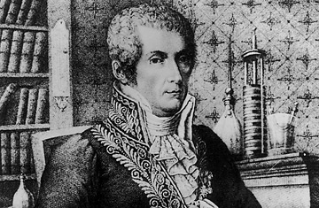
- Alessandro Volta

- Towards the late 19th century, Volta' concept of the closed-loop circuit inspired Inventors like Thomas Elva Edison to create a system of circuits to power the famous and world changing "light bulb". Starting with western society, the industrial revolution was propelled by the powering and illuminating of cities by light bulbs.
- Electric circuits involve both direct current, DC, and alternating current, AC. Direct current, current that only flows in one direction, was first used by Thomas Edison for his electric power transmission. Alternating current, current that alternates directions, was first discovered by Nikola Tesla while he was looking for a way to allow power transmissions to travel longer distances than direct current could.

- Thomas Edison

- Gustav Robert Kirchhoff was the main contributor to understanding how circuits worked. He was born March 12, 1824 and died on October 17, 1887. In 1845, Kirchhoff suggested what is now known as "The Node Rule" to model the conservation of charge around a closed-loop circuit. As a renowned German physicist, he proposed the principles that are now universally accepted laws surrounding the way that circuits function.
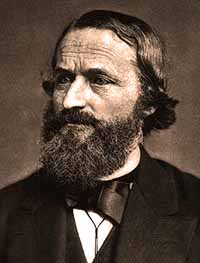

- Gustav Kirchhoff
See also
- Ohm's Law
- Resistors and Conductivity
- Current
- Ammeters,Voltmeters,Ohmmeters
- Power in a circuit
- RL Circuit
- LC Circuit
Further reading
- Matter & Interactions, Vol. II: Electric and Magnetic Interactions, 4nd Edition by R. Chabay & B.Sherwood (John Wiley & Sons 2015)
External links
References
- "All About Circuits - Electrical Engineering & Electronics Community." All About Circuits - Electrical Engineering & Electronics Community. Web. 30 Nov. 2015.
- "Build Electronic Circuits - Electronics Explained in a Simple Way." Build Electronic Circuits. Web. 30 Nov. 2015.
- Maria, Ana. “Thomas Alva Edison And His Light Show Of Menlo Park, New Jersey Happened 139 Years Ago.” The Awesome Daily - Your Daily Dose of Awesome, The Awesome Daily, 2 Jan. 2018, https://theawesomedaily.com/thomas-alva-edison-light-bulb/.
- Matter & Interactions, Vol. II: Electric and Magnetic Interactions, 4nd Edition by R. Chabay & B.Sherwood (John Wiley & Sons 2015)
- “Resistor Fundamentals " Resistor Guide.” RSS, http://www.resistorguide.com/fundamentals/.
- Soclof, Sidney. HowStuffWorks. HowStuffWorks.com. Web. 30 Nov. 2015.