RL Circuit
Written by Jiwon Yom


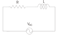
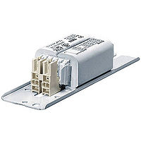
The RL circuit is one of the simple circuit applications and is composed of a power source, a resistor and an inductor. Figure 1 illustrates a symbolic representation of a simple RL circuit. Typically, an inductor in the RL circuit is a solenoid. The RL circuit can be frequently seen in fluorescent light choke, also known as electrical ballast (Figure 2), where the RL circuit limits the current that flows through the fluorescent light tube in order to prevent destruction of the tube.3 Also, the RL circuit can act as a high-pass or low-pass filter for voltage supply of varying frequencies.4
The Main Idea
A Mathematical Model
Let's take a look at the simple RL circuit illustrated in Figure 1. Before we examine the RL circuit, we must examine the effects of an inductor. An inductor is a coiled current-carrying wire. Due to its coiled structure, it surrounds a certain area where the magnetic field is varying over time. When the inductor is connected to a power source, current flows through the coil and such change in current leads to an additional emf in the coil. As Faraday’s law in motional emf shows that the magnitude of emf is equal to the magnitude of rate of change in magnetic flux, we can calculate the magnitude of emf produced by the inductor.
[math]\displaystyle{ |{emf}| = N|\frac{d\Phi}{dt}| }[/math], where [math]\displaystyle{ \Phi = N\frac{\mu_0I}{l}\times\pi r^2 }[/math], [math]\displaystyle{ N = }[/math] the number of coils in an inductor, [math]\displaystyle{ r = }[/math] radius of the coil, and [math]\displaystyle{ l = }[/math] the length of the inductor.
[math]\displaystyle{ emf = N \frac{d}{dt}[N\frac{\mu_0I}{l}\pi r^2] }[/math]
Since N, [math]\displaystyle{ \mu_0 }[/math], [math]\displaystyle{ \pi }[/math], and [math]\displaystyle{ r }[/math] are constants,
[math]\displaystyle{ emf = \frac{\mu_0N^2}{l}\pi r^2\frac{dI}{dt} }[/math]
Here, the terms [math]\displaystyle{ \frac{\mu_0N^2}{l}\pi r^2 }[/math] is a proportionality constant called "inductance" and can be summed up by letter L. Therefore, we can get the magnitude of emf of the inductor, which is given by
[math]\displaystyle{ emf_{inductor} = L\frac{dI}{dt} }[/math]
Going back to the RL circuit, now we can apply conservation of energy in circuit (loop rule) to the RL circuit. By the law of conservation of energy, we can obtain the following result.
[math]\displaystyle{ \Delta V_{battery} + \Delta V_{resistor} + \Delta V_{inductor} = 0 }[/math]
[math]\displaystyle{ emf_{battery} - IR - L\frac{dI}{dt} = 0 }[/math]
From this point, [math]\displaystyle{ emf_{battery} }[/math] will be shortened to [math]\displaystyle{ emf }[/math]. Rearrange the above result to solve for [math]\displaystyle{ I }[/math].
[math]\displaystyle{ \frac{dI}{dt} = \frac{emf-IR}{L} }[/math]
Using separation of variables,
[math]\displaystyle{ \frac{dI}{emf-IR} = \frac{dt}{L} }[/math]
[math]\displaystyle{ \int\frac{dI}{emf-IR} = \int\frac{dt}{L} }[/math]
Solving the integrals, we obtain
[math]\displaystyle{ -\frac{ln(emf-IR)}{R} = \frac{1}{L}t + C }[/math]
Since I = 0 when t = 0, [math]\displaystyle{ C = -\frac{ln(emf)}{R} }[/math], thus
[math]\displaystyle{ -\frac{ln(emf-IR)}{R} = \frac{1}{L}t - \frac{ln(emf)}{R} }[/math]
[math]\displaystyle{ ln(emf-IR) - ln(emf) = -\frac{R}{L}t }[/math]
[math]\displaystyle{ ln(\frac{emf-IR}{emf}) = -\frac{R}{L}t }[/math]
[math]\displaystyle{ \frac{emf-IR}{emf} = e^{-\frac{R}{L}t} }[/math]
[math]\displaystyle{ IR = emf - emf\times e^{-\frac{R}{L}t} }[/math]
[math]\displaystyle{ I = \frac{emf}{R}(1 - e^{-\frac{R}{L}t}) }[/math]
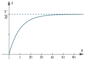
Therefore, when the circuit is connected, the current in the RL circuit increases exponentially over time to the maximum value of [math]\displaystyle{ \frac{emf}{R} }[/math]. Due to such sluggishness caused by time-varying current, the RL circuit is a useful tool to control the current.
A Computational Model

From the above section we were able to see that the current in the RL circuit grows exponentially over time. Figure 4 shows the exponential growth of the current in the RL circuit. For large t, we see that the exponential component becomes zero and thus we obtain [math]\displaystyle{ I = \frac{emf}{R} }[/math]. This is when the RL circuit reaches steady state and the current does not change due to steady magnetic flux in the inductor. In RL circuit, there is a value of t for which the exponent of the exponential component becomes a whole number. In other words, [math]\displaystyle{ t = \frac{L}{R}, \frac{2L}{R}, \frac{3L}{R}, \ldots, \frac{nL}{R} }[/math]. This time step is called "time constant" denoted by the Greek letter [math]\displaystyle{ \tau }[/math].
For [math]\displaystyle{ t = \tau }[/math],
[math]\displaystyle{ I = \frac{emf}{R}(1 - e^{-(\frac{R}{L})(\frac{L}{R})} }[/math]
[math]\displaystyle{ I = 0.632\frac{emf}{R} }[/math]
Hence, in the RL circuit, 63.2% of the maximum current is attained after the first time constant.
For [math]\displaystyle{ t = 2\tau }[/math],
[math]\displaystyle{ I = \frac{emf}{R}(1 - e^{-(\frac{R}{L})(\frac{2L}{R})} }[/math]
[math]\displaystyle{ I = 0.865\frac{emf}{R} }[/math]
Hence, in the RL circuit, 86.5% of the maximum current is attained after the second time constant.
For [math]\displaystyle{ t = 3\tau }[/math],
[math]\displaystyle{ I = \frac{emf}{R}(1 - e^{-(\frac{R}{L})(\frac{3L}{R})} }[/math]
[math]\displaystyle{ I = 0.950\frac{emf}{R} }[/math]
Hence, in the RL circuit, 95.0% of the maximum current is attained after the third time constant.
Generally speaking, after the fifth time constant, we assume that the circuit has reached steady state and therefore maximum current [math]\displaystyle{ I = \frac{emf}{R} }[/math]
[math]\displaystyle{ }[/math] [math]\displaystyle{ }[/math] [math]\displaystyle{ }[/math]
Examples
Theoretical
After the steady state has been reached and the current has reached its maximum value, you attempt to open the circuit. In the short period of time when you open the circuit, what would you expect to happen?
[math]\displaystyle{ Solution \: }[/math] When you open up the circuit, the current [math]\displaystyle{ I }[/math] drops from its maximum value to zero. We've observed that the emf across the inductor depends on [math]\displaystyle{ \frac{dB}{dt} }[/math] which is ultimately affected by and proportional to [math]\displaystyle{ \frac{dI}{dt} }[/math]. In the short period of time when you break the circuit, the change in the current is very large, and thus very large [math]\displaystyle{ \frac{dI}{dt} }[/math] is resulted and leads to very large emf across the inductor due to the large [math]\displaystyle{ \frac{dB}{dt} }[/math]. Therefore, when you open the circuit, you would observe sparks on the switch.
Numerical
How much time is required for the RL circuit composed of one [math]\displaystyle{ 1.5V }[/math] battery, a resistor resistance of [math]\displaystyle{ 0.5\Omega }[/math] and an inductor with inductance of [math]\displaystyle{ 0.03H }[/math] to reach 60% of the maximum current?
First, we find the maximum current.
[math]\displaystyle{ \begin{align*} I &= \frac{emf}{R} \\ &= \frac{1.5V}{0.5\Omega} \\ &= 3A \end{align*} }[/math]
Then, 60% of the maximum current would be
[math]\displaystyle{ \begin{align*} 0.6I &= 0.6(3A) \\ &= 1.8A \\ \end{align*} }[/math]
Finally, we can plug in the given information to the RL circuit current equation obtained from previous sections to find [math]\displaystyle{ t }[/math].
[math]\displaystyle{ I = \frac{emf}{R}(1 - e^{-(\frac{R}{L})t}) }[/math]
[math]\displaystyle{ 1.8A = 3A(1 - e^{-(\frac{0.5\Omega}{0.03H})t}) }[/math]
[math]\displaystyle{ e^{-(\frac{0.5\Omega}{0.03H})t} = 0.4 }[/math]
[math]\displaystyle{ \begin{align*} -(\frac{0.5\Omega}{0.03H})t &= ln(0.4) \\ &= -0.916 \\ \end{align*} }[/math]
[math]\displaystyle{ (\frac{0.5\Omega}{0.03H})t = 0.916 }[/math]
[math]\displaystyle{ \therefore t = 0.0550\: second }[/math]
References
3. https://en.wikiversity.org/wiki/RL_Circuit
4. http://www.electrical4u.com/rl-circuit-transfer-function-time-constant-rl-circuit-as-filter/
5. https://en.wikipedia.org/wiki/Fluorescent_lamp
6. http://www.intmath.com/differential-equations/5-rl-circuits.php