Magnetic Field of Coaxial Cable Using Ampere's Law
Edited by Joe Zein Fall 2017; Later Edited by David Hammett Fall 2017;
The Main Idea
A coaxial cable is a type of cable used as a transmission line in many modern electronics.
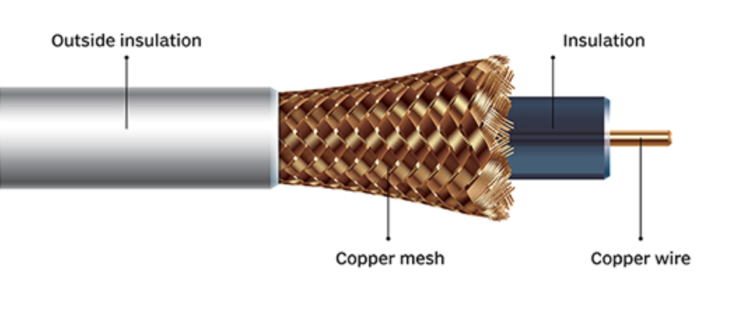
Coaxial cables are so named because they are comprised of two cylindrical conductors that share a central axis (the center of the cable.) The inner cylinder carries the current in one direction, is surrounded by an insulating region, and a second cylinder outside of that region carries current in the opposite direction, and they are both concentric along the same axis of the center of the wire. An outer insulating layer often surrounds this outer region to protect the second conductor.
Coaxial cables are common household items used in many electronics because of their ability to block external interference from other electromagnetic fields and for their ability to carry currents over long distances and to be able to exclusively carry their signal in the region between the two conductors.
The magnetic field of a coaxial cable can easily be found by applying Ampere's Law!
A Mathematical Model
Ampere's Law
We know that moving charges create a curly magnetic field around their trajectories by the Biot-Savart Law.
As a result, a current-carrying wire creates a curly magnetic field around it. This magnetic field curls around the center of the wire.
We can turn this observation around and note that if there is a curly magnetic field around some region, some current must be flowing through that region. We quantify this relationship through Ampere's Law.
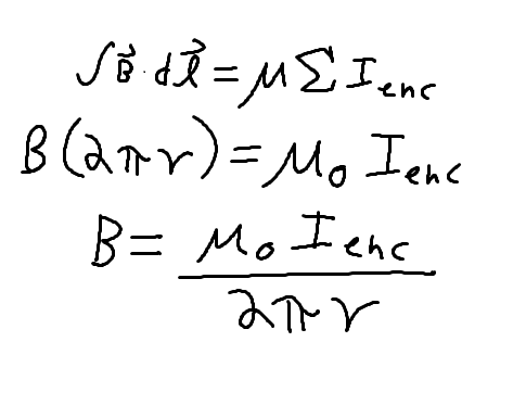
Ampere's Law quantifies the relationship between: 1-the sum of the magnetic field measured at infinitely many points around a path AND 2-the current enclosed in that path.
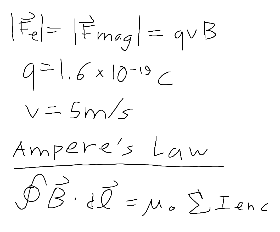
Another way to express the relationship described by Ampere's Law is that the path integral (represented by the integral with an inscribed circle in the equation below) of magnetic field along a closed path is equal to the sum of the current flowing up through that curved path times the constant mu-naught, which is the vacuum permeability, equivalent to exactly 4*pi*10^(-7).
A Computational Model
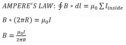
When considering calculations using Ampere's law for coaxial cables, simply realize that we may draw a boundary curve around the 2-dimensional region that we wish to investigate, and relate the path integral of the magnetic field along this curve to the current going through that region using Ampere's law.
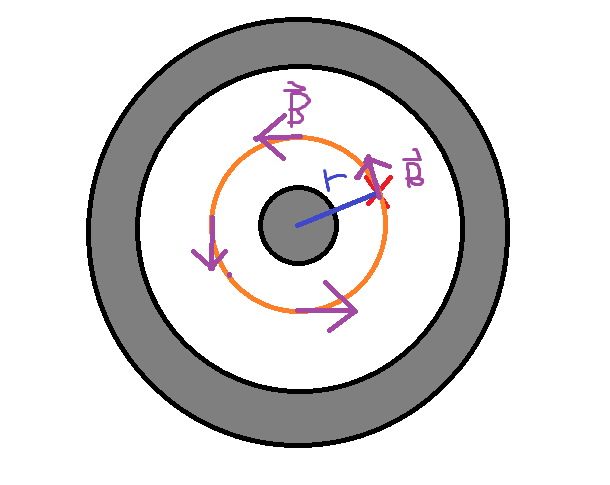
In the case of a coaxial cable, these currents differ in direction (and may differ in magnitude), but they share a common center. Therefore, if we wish to learn about the magnetic field at certain points inside or outside of a coaxial cable, we need only draw a boundary curve around the radius from the center of these two current-carrying wires at the location at which we desire to investigate the magnetic field, and note that the magnetic field will be uniform in magnitude (but not in direction) everywhere along that surface. (The direction will always be parallel to the path and perpendicular to the radius line at that point.) Since this field is uniform, we may simply write that the magnitude of magnetic field B is equal to the product of the enclosed current and mu-naught divided by the circumference, along which the magnetic field-distance product is uniform. See the diagram and derivation below for further explanation of this.
Simple Example Problem
Imagine a coaxial cable with more current flowing into the page (forward) than out of the page. What direction would the curly magnetic field around the coaxial cable have?
It is easy to realize that the net current flowing into the page is all that matters, since our Amperian surface would surround the coaxial cable and simply add up all the current inside, depending upon the direction of each current contributor. So, with net current flowing into the page, the right-hand rule tells us that the direction of curly magnetic field would be clockwise around the cable.
Middling Example Problem
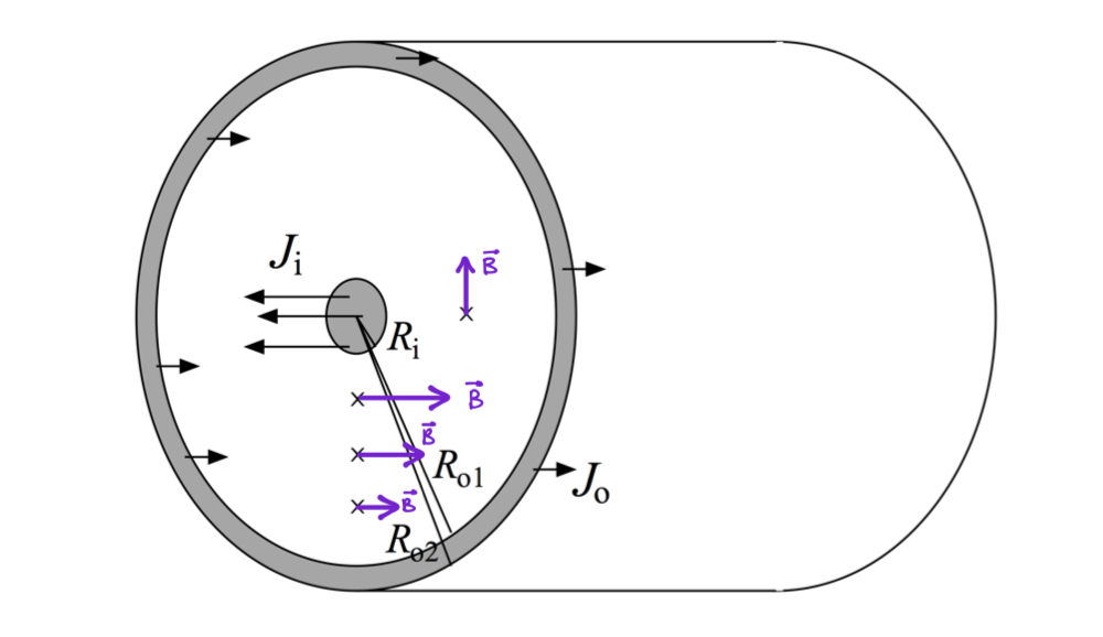
Current flows up the inner conductor and returns down the outer conductor. The inner conductor has radius Ri; the outer conductor is a cylindrical shell with inner radius Ro,1 and outer radius Ro,2. Currents in the inner and outer conductors are uniformly distributed throughout their cross-sectional areas with densities (current/area) Ji and Jo, respectively. Ji =2000A/m2;Ri =0.3mm;Ro,1 =2.0mm;Ro,2 =2.1mm.
The goal here is to determine magnitude and direction of magnetic fields at different locations in and out the wire.
For this, we simply have to apply Ampere's Law to the problem and imagine an Amperian surface with a radius of r:
Case A: Ri< r < Ro,1.
Direction.
To evaluate direction we make use of the right hand rule. The current enclosed by a circle of radius r is the current carried by the central wire. It points out of the page. If we put our thumb in this direction, we see our fingers curling Counterclockwise. The purple arrows show the direction of B at different locations (different r).
Magnitude.
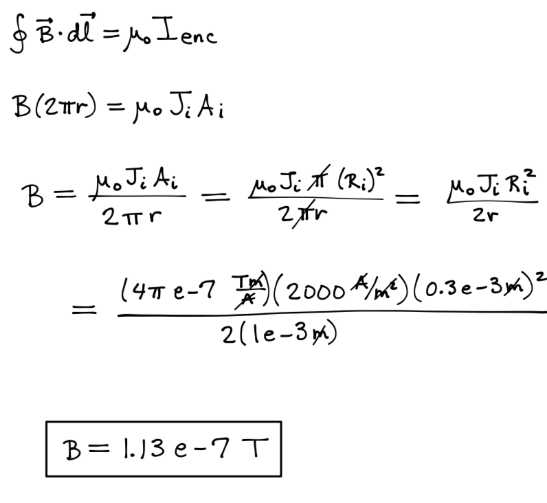
We know that:.
What would the magnitude of the magnetic field be at r = 1mm?
Case B: r > Ro,2.
Magnitude.
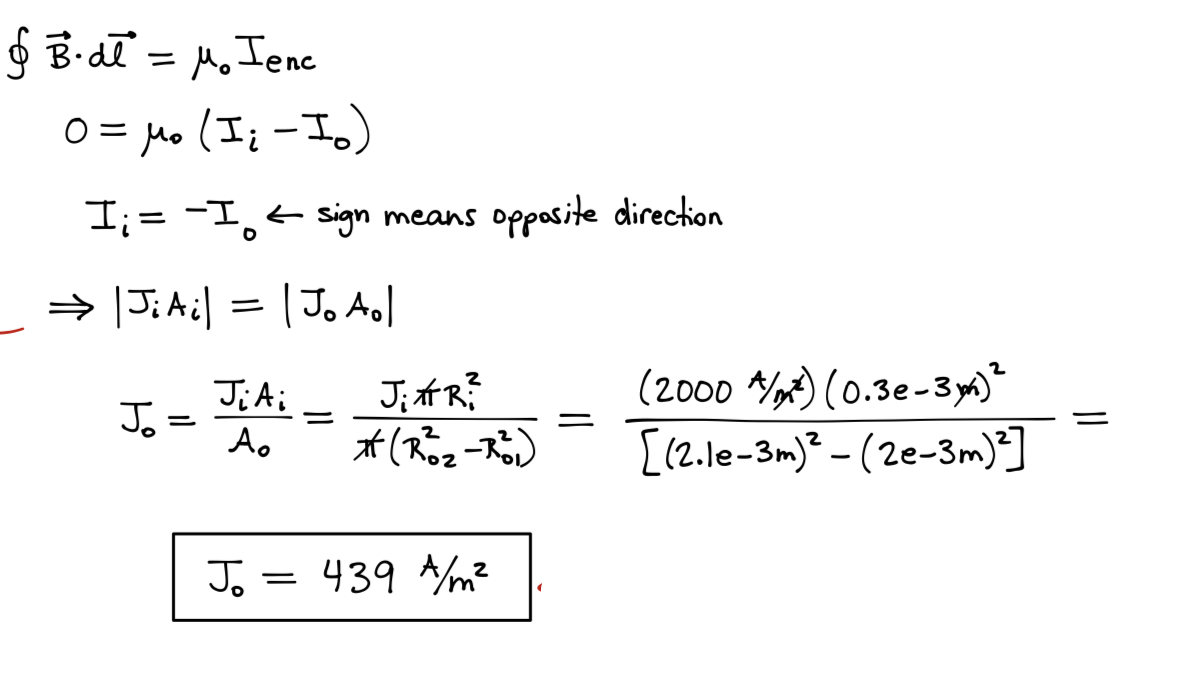
Show that B would be zero if and only if current is equal and opposite in direction. Also, calculate J_not, the current density in the outer copper wire.
Conclusion.
To conclude, we now know that the coax produces no magnetic field outside the wire as long as current in each wire are equal in magnitude and opposite in direction. We also know how to evaluate the field anywhere in and out the wire as long as we know the current enclosed.
Difficult Example Problem
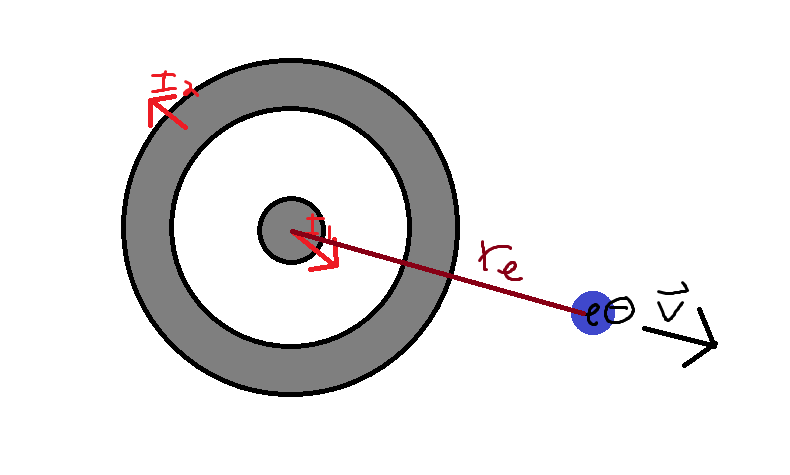
Consider a coaxial cable with a 20 Amp current flowing outward from the middle conductor, and a 10 Amp current flowing inward through the outer conductor. Let there be an electron at a radius of 1 meter away from the center of the coaxial cable moving at a speed of 1 meter per second parallel to this radius. What would be the acceleration on the electron due to the magnetic force produced by this cable that acts on the electron?
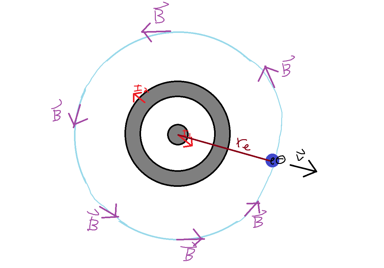
Consider the following diagram of this scenario.
We now write the equation for the force on the electron, which we will use later to find the acceleration on the electron. Realize that the equation for magnetic force reduces to Fm = qvB because the angle between the magnetic field vector and the electron's velocity vector is 90 degrees, because that velocity was said to be parallel to the line between the electron and the center of the coaxial cable; thus, Fm = qvB*sin(90 degrees) = qvB. We note that we have all relevant information to find this force except for the magnitude of the magnetic field at the location of the electron. We must find this magnetic field. We write Ampere's law, for reference.
In order to apply Ampere's law, we must draw an Amperian loop around the region we wish to investigate. The question is: where should we draw our Amperian loop, and what should it look like?
Well, we know we want our Amperian loop to contain the center of our electron, and ideally, we would like to draw our Amperian surface such that the magnetic field that is present along it is uniform at every point along it. This way, we can consider the magnetic field B and the length of this path L as separate entities, not tied to each other in their expressions, and thus isolate B.
We can make the magnetic field B have uniform magnitude by making every point along our Amperian loop be equidistant from the center of all of the current in the cable. We can accomplish this by drawing our Amperian loop as a circle with its center at the center of the coaxial cable, and by ensuring that the loop coincides with the center of the coaxial cable.
This is shown in the diagram below, where the new blue circle is our Amperian loop and the purple vectors represent the magnetic field at several points along that surface. Note that we have already determined the direction of this magnetic field; it is counterclockwise relative to this surface; since the majority of the current is flowing outward rather than inward, the right-hand rule tells us that the magnetic field will point counterclockwise around this loop.
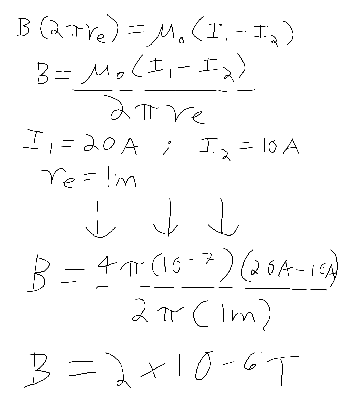
We are now in a position to evaluate our earlier expression for Ampere's Law. We evaluate the path integral of magnetic field along the length of the path, recognizing that it is uniform along this path, which has length L equal to the circumference of this circle, which is 2*pi*(radius of the electron). The current enclosed is written as the inner current minus the outer current, because these currents flow in opposite directions and thus oppose each other (10 Amps of the inner conductor are canceled out by the 10 total Amps flowing through the outer conductor.) We evaluate the magnetic field at the location of the electron (which is the same as at all locations along this Amperian loop) as 2*10^(-6) Teslas.
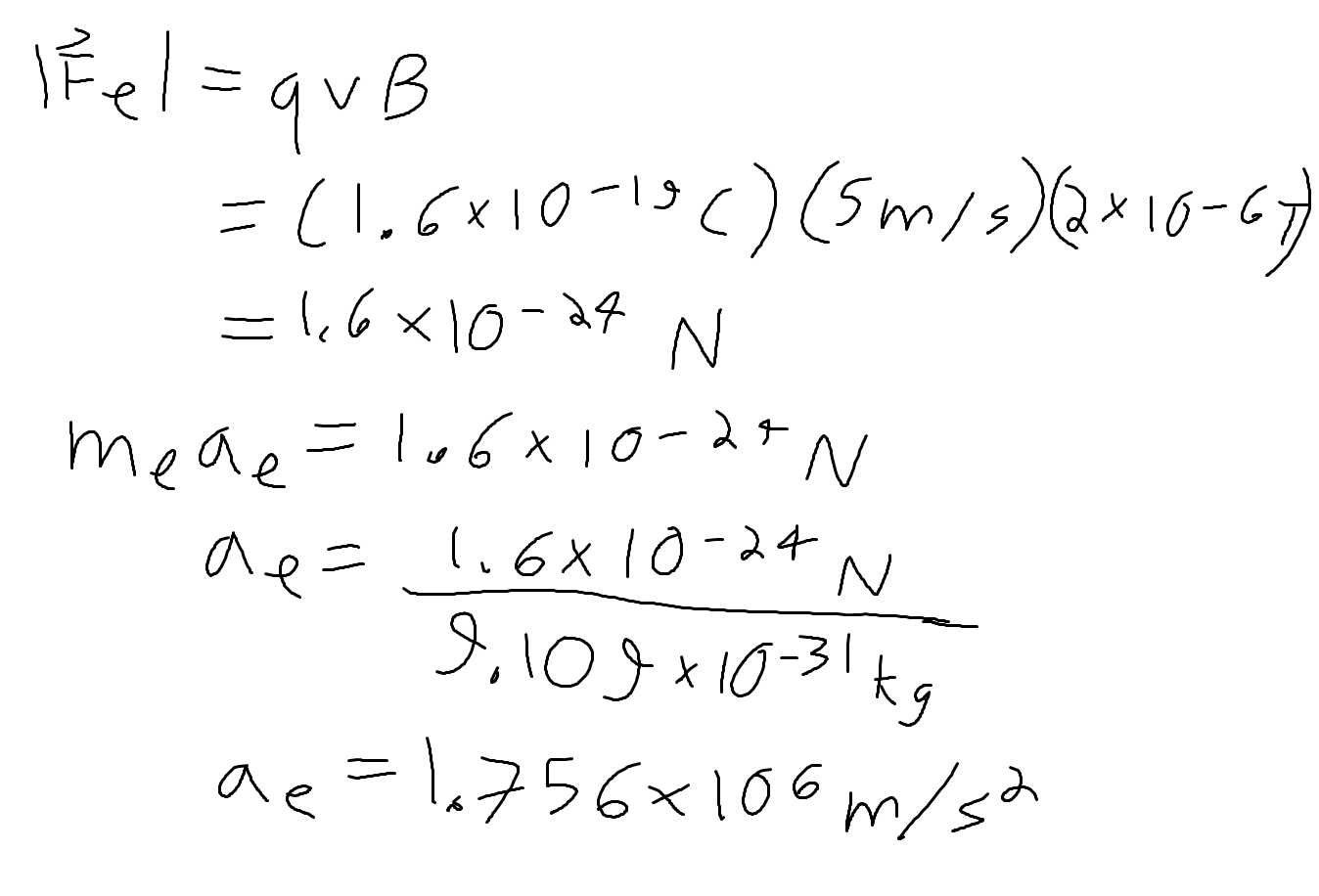
We now return to our previous expression for the magnitude of the magnetic force on the electron. We plug in our calculated value for the magnetic field B, as well as our given value for velocity (1m/s) and the magnitude of the charge of an electron (1.6*10^(-19)C) to find the magnetic force on the electron. Finally, we divide that force by the mass of an electron, which is about 9.1*10^(-31)kg to find the acceleration of this electron. We find that it is about 1.76*10^(6)m/s^2.
What would be the direction of this acceleration? This acceleration would be in the same direction as the force that engendered it, which was the magnetic force. Use the right hand rule with the second diagram above to note that the magnetic force would point into the page in this case. Remember to take the sign of q, which is negative, because our object of interest is an electron and is thus negatively charged, into account!
Connectedness
How is this topic connected to something that you are interested in? How is it connected to your major? Is there an interesting industrial application?
This topic is connected to my interest in how the all-permeating electric and magnetic fields of wires might be insulated and both protected from outside interference, and stopped from creating their own interference, since the design of a coaxial cable accomplishes both.
The main advantage of coaxial cables is that, as we've demonstrated, they do not produce any magnetic field outside of it, so long as the "net" current running through the axis of the cable is zero at all points. This is an advantage because it allows these cables to be installed next to metals without losing power due to interference. This design also prevents any interference coming from outer space!
Electrical engineering:. Coax cables are used in transmission of signals. Thus they have tons of applications in Its applications include feedlines connecting radio transmitters and receivers with their antennas, computer network (Internet) connections, digital audio (S/PDIF), and distributing cable television signals.
Chemical engineering:. Coaxial cables are often used in design of important machinery because they minimize the effects of interference. In designing a complex reactor setup, where a multitude of electric devices are guaranteed to be in use for monitoring the process and for driving the process forward, this key advantage of coaxial cables would be important to consider in the design of equipment for such a reactor.
History
Oliver Heaviside designed the Coaxial Cable in 1880 in England. Over the years the cable was enhanced before its use as the first transatlantic cable in 1956. The cable was, as mentioned, was developed due to its advantages over previous cables in that it provides constant conductor spacing and resistance over electromagnetic interference, making it useful in long distance transmission lines.
In the 1930's, the coaxial cable design was first used in televisions, where it was used to broadcast the 1936 Summer Olympics.
In 1956, the first transatlantic coaxial cable was laid. Known as TAT-1, this cable was used for communication between peoples and the heads of states of various nations. It cost about 120 million British pounds to construct, and remained in use for 22 more years until it was retired in 1978, in favor of several newer cables.
Below is a photo of a section of TAT-1, with more layers removed higher up the cable. Note the differences between the sections; how some appear to be more conducting (the metallic sections) than others; this follows our discussion of coaxial cable exactly!
See also
Page for Ampere's Law: Ampere's Law
More applications: Magnetic Field of a Toroid Using Ampere's Law and Magnetic Field of a Long Thick Wire Using Ampere's Law
External links
https://www.youtube.com/watch?v=IMoN6MVgOgA
References
Chabay, Sherwood. (2011). Matter and Interactions (3rd ed.). Raleigh, North Carolina: Wiley.
Coaxial cable. (n.d.). Retrieved November 27, 2016
"Specimen of the first transatlantic telephone cable, 1956". The Science Museum.
http://atlantic-cable.com/Souvenirs/1956TAT-1/
https://web.archive.org/web/20071203011029/http://www.earlytelevision.org/1936_olympics.html
Exam 4 Fall 2015 Question 3
