Rectification (Converting AC to DC)
Rectification is the conversion of alternating current (AC) to direct current (DC). This is performed by a device that only allows one-way flow of electrons (a rectifier).
The Main Idea
Rectification is the conversion of alternating current to direct current. Rectification is performed by a diode that allows current to flow in one direction but not in the opposite direction. Direct current that has only been rectified, however, has various changes in voltage lingering from the alternating current. Capacitors are used to smooth the current and make it even.
The simplest kind of rectifier circuit is the half-wave rectifier. Only one half of an AC waveform to pass through to the load.
To rectify AC power to obtain the full use of both half-cycles of the sine wave, a different rectifier circuit configuration may be used. Such a circuit is called a full-wave rectifier.
A Mathematical Model
For the half-wave rectifier, only one half of the wave is passed, so the output voltage is lower:
[math]\displaystyle{ \begin{align} V_\mathrm {rms} &= \frac{V_\mathrm {peak}}{2}\\ V_\mathrm {dc} &= \frac{V_\mathrm {peak}}{\pi} \end{align} }[/math]
Vrms: the root-mean-square value of output voltage
For a full-wave rectifier, the following voltages are:
[math]\displaystyle{ \begin{align} V_\mathrm {dc}=V_\mathrm {av}&=\frac{2V_\mathrm {peak}}{\pi}\\ V_\mathrm {rms}&=\frac {V_\mathrm {peak}}{\sqrt 2} \end{align} }[/math]
Efficiency
The power efficiency for rectifiers is defined as the ratio of input power (AC) to output power (DC). Energy is lost from the conversion creating ripples, but can be maximized through the use of capacitors and smoothing.
- [math]\displaystyle{ P_\mathrm {in} = {V_\mathrm {peak} \over 2} \cdot {I_\mathrm {peak} \over 2} }[/math]
(the divisors are 2 rather than √2 because no power is delivered on the negative half-cycle)
- [math]\displaystyle{ P_\mathrm {out} = {V_\mathrm {peak} \over \pi} \cdot {I_\mathrm {peak} \over \pi} }[/math]
Thus maximum efficiency for a half-wave rectifier is,
[math]\displaystyle{ \eta = {P_\mathrm {out} \over P_\mathrm {in}} = \frac{4}{\pi^2} = 40.6% }[/math]
Similarly, for a full-wave rectifier,
[math]\displaystyle{ \eta = {P_\mathrm {out} \over P_\mathrm {in}} = \frac{8}{\pi^2} = 81.1% }[/math]
A Computational Model
Examples
Below is a half-wave rectifier circuit.
For most power applications, half-wave rectification is poor. Furthermore, the AC power source only supplies power to the load one half every full cycle, meaning that half of its capacity is unused. However, it can be a simple way to reduce power to a resistive load. For example, a light may at full power be using AC, but changing to half-wave and rectified, will be half power.
To rectify AC power and utilize both negative and positive, a different configuration must be used. One kind of full-wave rectifier, called the center-tap design, uses a transformer with a center-tapped secondary winding and two diodes, as in figure below.
This circuit’s operation is easily understood one half-cycle at a time. Here is the first half-cycle. At this time, only the top diode is conducting; the bottom diode is blocking current, and the load “sees” the first half of the sine wave, positive on top and negative on bottom. Only the top half of the transformer’s secondary winding carries current during this half-cycle as in figure below.
During the next half-cycle, the AC sign reverses. Now, the other diode and the other half of the transformer’s secondary winding carry current while the portions of the circuit formerly carrying current during the last half-cycle sit idle. The output still shows the same wave as before, but the input is just reversed.
Another, more popular full-wave rectifier design exists, and it is built around a four-diode bridge configuration. This is called the full-wave bridge (Figure below)
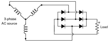
One advantage of remembering this layout for a bridge rectifier circuit is that it expands easily into a polyphase version in Figure below. In this scheme, the output of one diode connects to the input of another, creating multiple phases of what is connecting to the route power.
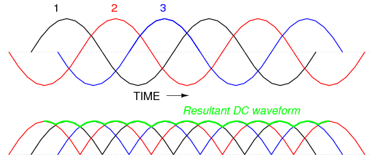
When this polyphase rectifier is used, (see the figure below), the output voltage is smoother compared to the center-tapped configuration. This design is beneficial for products that require the power of AC, but also need the smoothness and less noise from DC.
Connectedness
Imagine you're sitting on a plane. A scary guy goes up to you, "What does rectify mean, and if you don't give me the right answer, we're going down."
Now I'm scared.
What does he mean?
A dictionary and my mom define it as, "to remedy, or make right," but is that what he means? Should I "rectify" his problems?
No, this guy's crazy
"Sir, I'll give you your answer, yesterday I "rectifyd" my drawer by manipulating its alternating current to produce a direct current, with only 75% power loss. Sir."
The scary guy says: "Good, thanks, bye."
Your life is saved.
History
Put this idea in historical context. Give the reader the Who, What, When, Where, and Why.
See also
References
http://www.allaboutcircuits.com/textbook/semiconductors/chpt-3/rectifier-circuits/
http://www.global.tdk.com/news_center/publications/power_electronics_world/pdf/aaa60607.pdf
http://www3.nd.edu/~lemmon/courses/ee224/web-manual/web-manual/lab8b/node6.html


