RL Circuits
RL Circuits CLAIMED BY VJ SERVERA
The Main Idea
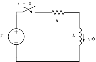
An RL circuit is one that contains resistors and inductors. The simplest type of these circuits involves one resistor and one inductor, and is called a first order RL circuit. The order of the circuit is equal to the number of inductors involved in the circuit. In this section we will study the following circuit:
A Mathematical Model
First we must remember the relationship between current going through an inductor and the voltage drop across it. The relationship is simply
[math]\displaystyle{ {L\frac{d\vec{i}}{dt}} = \vec{v(t)} }[/math]
meaning that the derivative of the current going through the inductor is proportional to the voltage drop across it. The proportionality constant is the inductance [math]\displaystyle{ L }[/math].
Before the switch closes, we know there is no current going through the inductor , and therefore no voltage. The initial conditions are:
[math]\displaystyle{ v(0) = 0 }[/math]
[math]\displaystyle{ i(0) = 0 }[/math]
Now applying Kirchoff's Voltage Law (loop-rule) we obtain the first order differential equation:
[math]\displaystyle{ V = iR + L\frac{di}{dt} }[/math]
Now we solve the equation. Rearranging:
[math]\displaystyle{ \frac{di}{dt} = \frac{V-iR}{L} }[/math]
[math]\displaystyle{ \frac{di}{V-iR} = \frac{dt}{L} }[/math]
Integrating both sides:
[math]\displaystyle{ -\frac{\ln(V-iR)}{R} = \frac{t}{L} + K }[/math]
Since [math]\displaystyle{ i = 0 }[/math] when [math]\displaystyle{ t = 0 }[/math], plugging these values in gives us
[math]\displaystyle{ K = -\frac{\ln(V)}{R} }[/math]
Substituting K back into our equation, getting rid of the denominator, and collecting the logarithms, we have
[math]\displaystyle{ \ln(\frac{V-Ri}{V}) = -\frac{R}{L}t }[/math]
Exponentiating both sides and solving for [math]\displaystyle{ i }[/math]
[math]\displaystyle{ i = \frac{V}{R}(1 - e^{(-\frac{R}{L}t)}) }[/math]
Graph
If we multiply the value we derived for current by the resistance, we can also find the voltage across the inductor as time passes. We also must remember that instead of growing, the voltage will be decreasing as the current approaches a constant (see the relationship between the inductor's current and voltage drop, line 1 of the derivation above). Therefore, instead of the term
[math]\displaystyle{ 1 - e^{(-\frac{R}{L}t)} }[/math]
we will just have
[math]\displaystyle{ e^{(-\frac{R}{L}t)} }[/math]
Multiplying the equation for current we derived by the resistance, and keeping the line above in mind, we have
[math]\displaystyle{ V = V(e^{-\frac{R}{L}t}) }[/math]
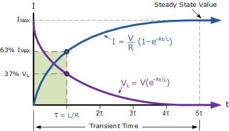
Graphing both [math]\displaystyle{ V }[/math] and [math]\displaystyle{ R }[/math] we have:
Time constant
The time constant τ is equal to [math]\displaystyle{ \frac{L}{R} }[/math] and is a way of relating the resistance and inductance to a point in time at which 67% of the max current has been reached or 67% of the voltage has decayed. This is because the term [math]\displaystyle{ e^{-\frac{Rt}{L}} }[/math] will always reduce to [math]\displaystyle{ e^{-1} }[/math], which is approximately equal to [math]\displaystyle{ 0.33 }[/math].
A Computational Model
This simple online applet shows how the current through the inductor behaves as time passes. Eventually, the inductor acts as a straight wire and the current through it is constant.
Examples
Example 1
What is the time constant for a series RL circuit with [math]\displaystyle{ R = 5 }[/math] Ohms, and inductance [math]\displaystyle{ L = 20 }[/math] mH?
Solution
[math]\displaystyle{ \frac{L}{R} = \frac{20 * 10^{-3}}{5} = 4 ms }[/math]
Example 2
Refer to the figure in the main idea section. Let the voltage source [math]\displaystyle{ V = 10 }[/math] volts, resistor [math]\displaystyle{ R = 5 }[/math] Ohms, and inductance [math]\displaystyle{ L = 20 }[/math] Henries. How long after the switch closes does the current through the inductor equal [math]\displaystyle{ 1.5 }[/math] amps? What is the final current going through the conductor?
Solution Solve for time [math]\displaystyle{ t }[/math].
[math]\displaystyle{ i = \frac{V}{R}(1 - e^{(-\frac{R}{L}t)}) }[/math]
[math]\displaystyle{ 1 - \frac{iR}{V} = e^{(-\frac{R}{L}t)} }[/math]
[math]\displaystyle{ \ln(1 - \frac{iR}{V}) = -\frac{R}{L}t }[/math]
[math]\displaystyle{ -\frac{L}{R} * \ln(1 - \frac{iR}{V}) = t }[/math]
Substitute values:
[math]\displaystyle{ t = 5.5 s }[/math]
Connectedness
1. How is this topic connected to something that you are interested in?
Im interested in how brain waves are read through EEGs. EEGs involve RL circuits to read brain signals properly and give that information to the viewer.
2. How is it connected to your major?
In biology, microscopes are used a lot to view cells and other extremely small objects. Some hardware additions to microscope use RL circuits to help images appear more clear to the viewer.
3. Is there an interesting industrial application?
RL circuits are used universally; anywhere signals from the outside, such as noise or light, are used for data or analysis, RL circuits allow for hardware to recieve these signals and filter out the ones that are important.
History
In the mid-19th century, Joseph Henry discovered the principle of self inductance. By wrapping coil around a magnet and sending a current through the coil, he realized that a magnetic field was created and energy could be stored in it through the "induced" voltage that is generated across the inductor. The history of inductors can be best shown through their many applications since their discovery. One of the most important applications that has been used almost universally in electronics and hardware since the 1800s was the filter. A filter is a circuit, which contains a combination of resistors, inductors, and capacitors, that can block signals of certain frequencies and let pass signals of other frequencies. This concept is heavily utilized in many fields; for example, in telecommunications, phones must contain filters that only let frequencies that come from the human voice pass through, and reduce other noise.
Another application of inductors lies in transformers. Transformers "transform" voltages from low to high and high to low. This is important because power plants store energy at very high voltages and low currents in order to minimize loss of energy. These voltages can get as high 750,000 volts. Of course, home appliances barely need a fraction of that. Inductors in circuits are used in transformers so that the high voltages from the power plants can be brought to lower, useable voltages.
See also
Further reading
Inductors in Electroencephalography
External links
References
This section contains the the references you used while writing this page

