Non Steady State
by Javier Rodriguez
The Main Idea
RC circuits in non-steady state are defined by changing charges, currents, and voltages as a function of time.
In other words, Q’(t) ≠ 0
Non-steady state circuits are specifically important when analyzing the charging or discharging a capacitor. Surely, when a capacitor fully charged (Q/C = Emf) or fully discharged (Q=0), the circuit is in steady state — the derivative of charge with respect to time is 0.
A Mathematical Model
The main two facets of non-steady state circuits, for the purposes of this course, cover the charging and discharging of capacitors. Mathematically, an exponential change occurs when the derivative of a quantity has a relation to the quantity itself. We'll be applying this to the charge and discharge of capacitors, with varying circuit arrangements dependent on switches. Note that throughout these examples, we'll be using the Loop Rule (more formally known as the Kirchoff's Voltage Rule) -- but not in terms of steady state. That is, the more familiar variation (∆Vloop = 0) doesn't apply in this case, as it details the circuit at the endpoints of the timeframe, or steady state. Through these few examples, we'll be looking at the intermediate moments of a given time frame.
Example 1: Charging a Capacitor
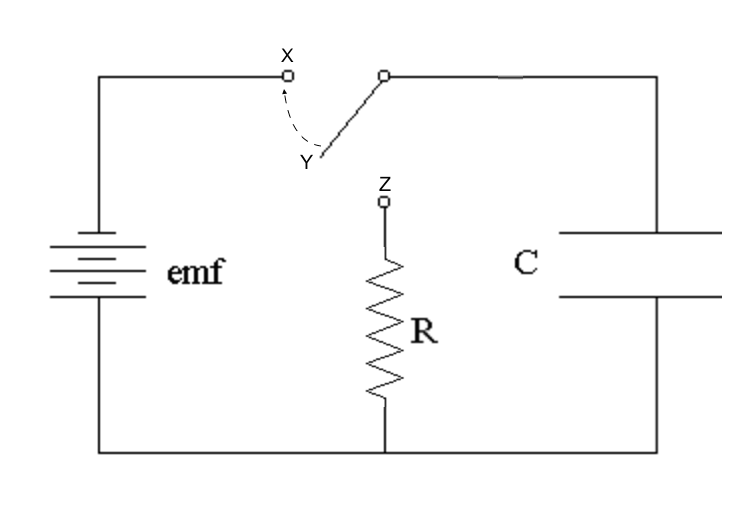
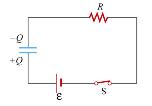
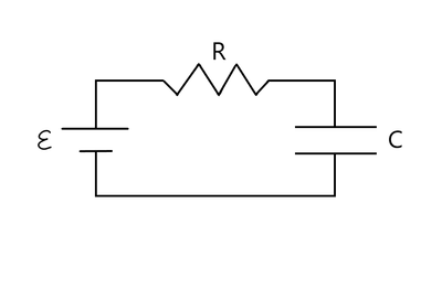
To better understand this, let’s take a look at a simple RC circuit consisting of a battery Emf, a resistor of resistance R, and a capacitor with a capacitance C.
Assume that the capacitor initially has a charge of Q=0. While the switch remains open at location Y, there is no current flowing through the circuit.
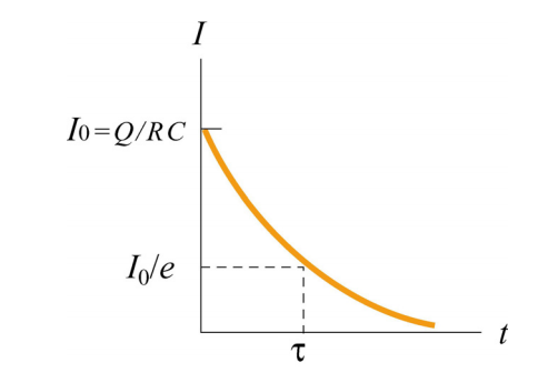
The moment the switch closes at location X, the voltage across the capacitor does not instantaneously equal the Emf of the battery. A current initially starts to flow, which allows charges to collect on the plates of the capacitor. At this moment, Q’(t) > 0. As time passes, the charges continue to build up, which permits less current to pass through the capacitor — causing the current to decrease under an exponential decay, I’(t) < 0.
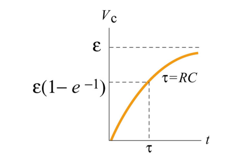
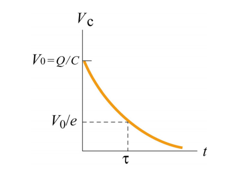
Because the voltage drop across a capacitor is directly proportional to charge, this voltage follows the same trend. To find the the exact voltage drop across the plates at any given time t, we can use the following exponential equations:
V(t) = Emf (1 - e-t/RC)
Looking at this equation, we see that as time increases, e-t/RC grows increasingly smaller. After enough time passes, this value will approximate at 0, leaving the voltage at time t to resemble:
V(t) = Emf
At this moment, the capacitor will be fully charged, and no current will flow through the circuit (refer to figure below)
Example 2: Discharging a Capacitor
Very similar to charging a capacitor, the discharging of a capacitor involves a time period when the derivatives of charge and current are nonzero. The given circuit is once again in non-steady state.
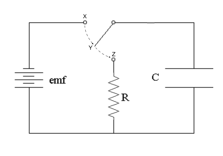
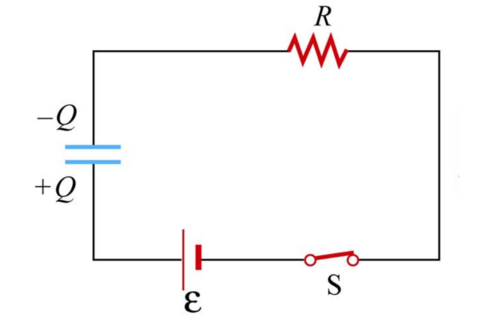
Consider the same circuit above. Assume the switch was at location X for a very long time, and the capacitor is fully charged.
The moment the switch is moved to location Z, the capacitor supplies a voltage, with an Emf equal to that of the battery. As current begins to flow, the charges on the plates grow increasingly smaller with time. Because of this, both the capacitor’s voltage and the current flowing through the circuit are also decreasing.
Using a slightly modified equation, we can also find the exact voltage of the capacitor at an arbitrary time t.
V(t) = Emf (e-t/RC)
Using this equation, we clearly see that initially at t=0, the voltage equals Emf. However, as the elapsed time gets larger, we notice that V(t) will grow increasingly smaller, eventually reaching an approximate value of 0. When this occurs, it indicates that the charges on the capacitor plates are also 0, meaning the current has stopped flowing.
It’s interesting to note that if the resistor were, for example, a lightbulb, the exponential decay of the current passing through the lightbulb would inevitably cause the lightbulb to shine its brightest at time t=0, and grow increasingly dimmer as the capacitor discharges. When the capacitor is fully discharged, as mentioned above, the current will be 0, and the lightbulb will go out.
Conceptual Review
Question:
An uncharged capacitor is connected to a DC voltage source via a switch. A resistor is placed in series with the capacitor. The switch is initially open. At t = 0, the switch is closed. A very long time after the switch is closed, the current in the circuit is:
A: nearly zero B: at a maximum and decreasing C: nearly constant but non-zero
Solution:
A. After a long time the current is 0
(1) After a long time the current is 0 Eventually the capacitor gets “full” – the voltage increase provided by the battery is equal to the voltage drop across the capacitor. The voltage drop across the resistor at this point is 0 – no current is flowing.
Question:
An uncharged capacitor is connected to a DC voltage source via a switch. A resistor is placed in series with the capacitor. The switch is initially open. At t = 0, the switch is closed. Just after the switch is closed, the current in the circuit is:
A. zero and increasing B. at a maximum and decreasing C. constant but non-zero
Solution:
B. B. at a maximum and decreasing
(1) Initially there is no charge on the capacitor and hence no voltage drop across it. All of the potential drop is across the resistor – maximum current. As charge builds up on the capacitor the current will “slow down” – there will be a smaller drop across the resistor and hence less current.
Conceptual Example: A Spark in the Capacitor --Kcrawford32 (talk) 02:06, 12 April 2016 (EDT)
A capacitor in the circuit below is initially uncharged. It is connected to a power supply and placed in series with a resistor, as shown. Once the current is running and the electric field in the capacitor gap increases to 3e6 N/C, a spark forms in the gap. When this happens, the air is then considered a conductor.
The resister has a resistance of 300 Ohms, is 10 cm long, and has a 5 mm radius. The capacitor has plate dimensions of 2 m by 2 m, and has a gap of .5 mm. The emf of the battery is 2000 Volts.
1. Just before you see the spark, what is the magnitude of the potential difference across the capacitor?
Because we are treating the capacitor as a conductor, we can use the equation for potential difference across a conductor. You can visualize it as a short wire.
This gives us:
deltaV = E*L, where E is the electric field in the capacitor when we see the spark, and L is the distance between the capacitor.
deltaV = (3e6 N/C) * (.0005) = 1500 V.
2. Just before you see the spark, what is the electric field in the resistor?
We know E = deltaV/L.
We also know that since the capacitor is still acting as a capacitor at the instance just before we see the spark, we know the current is still flowing in the circuit. Because of this fact, we know the magnitude flows from left to right in the positive x direction through the resistor. There is no y or z movement.
We know that because the current is still flowing at the instant before we see the spark, the voltage change around the circuit is 0.
We know that the three elements acting in the circuit are:
deltaV = 2000 V (from the battery) - IR - 1500 V (from above), where IR is the resistance of the resistor multiplied by the current.
This means IR = 500 V.
We also know that deltaV = IR = EL, so E must equal IR/L.
Plugging in, we get E = 500V/.1m = 5000 V/m.
3. Just before you see the spark, what is the conventional current through the resistor?
We know that deltaV = 2000 V (from battery) - IR - 1500 V (from #1).
Therefore, IR = 500 V (this is consistent with what we found in #2).
Because R is given, we can divide I by R to get 500 V / 300 Ohms = 1.67 A.
Connectedness
This topic is particularly relevant to Electrical and Computer Engineering majors. For more information on its applications, consult further reading below. This book provides further insight into RC circuits in general, both in steady state and non-steady state.
See also
- Steady State
- RC Circuits
- Node Rule
- Loop Rule
- Current
- Ohm's Law
Further reading
Turner, Rufus (1976), RC Circuits 1st edition, H. W. Sams, Oxford Press
External links
"RC Circuits Charging" (https://www.youtube.com/watch?v=OwbQLrNBDpY)
"RC Circuits Charging and Discharging Calculations" (https://www.youtube.com/watch?v=JHHikLqJuYk)
"RC Circuits, Charging Capacitors, Discharing Capactiors and Equations" (https://www.youtube.com/watch?v=6Kz2xas_vOE)
References
Direct Current Circuits - Massachusetts Institute of Technology (http://web.mit.edu/viz/EM/visualizations/coursenotes/modules/guide07.pdf)
RC Circuits - Massachusetts Institute of Technology (http://ocw.mit.edu/courses/physics/8-02t-electricity-and-magnetism-spring-2005/lecture-notes/prs_w05d1.pdf)

