Gyroscopes
__
A gyroscope is a device containing a wheel or disk that is free to rotate about its own axis independent of a change in direction of the axis itself. Since the spinning wheel persists in maintaining its plane of rotation, a gyroscopic effect can be observed.
The Main Idea
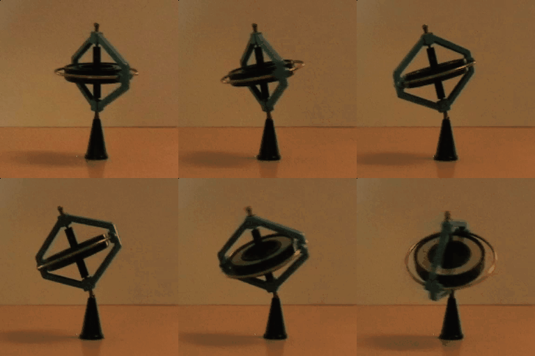
Although insignificant looking and seemingly uninteresting when still, gyroscopes become a fascinating device when in motion and can be explained using the angular momentum principle. Gyroscopes come in all different forms with varying parts. The main component of a gyroscope is a spinning wheel or a disk mounted on an axle. Typically gyroscopes contain a suspended rotor inside three rings called gimbals. In order to ensure that little torque is applied to the inside rotor, the gimbals are mounted on high quality bearing surfaces, allowing free movement of the spinning wheel in the middle. These types of gyroscopes with multiple gimbals are useful for stabilization because the wheels can change direction without affecting the inner rotor. If the spinning axle of a gyroscope is placed on a support, then a complex motion can be observed. The motion of a gyroscope will be modeled and explained in this page.
A Mathematical Model
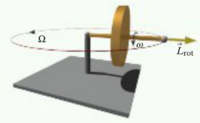
When the spinning axis of a gyroscope is placed on a support, a gyroscopic effect is observed. The gyroscope bobs up and down--nutation--and rotates about the support--precession. For the sake of simplifying the mathematical equations for a gyroscope's motion, nutation (the upwards and downwards movement of the rotor) will be ignored. We will only look at the precession motion of the gyroscope.

To start off with, the gyroscope's rotor rotates about its own axis with an angular velocity of ω and has a moment of inertia I. Thus, the rotational angular momentum of the rotor can be modeled as:
[math]\displaystyle{ L_{rot,r} = Iω }[/math]
Where the rotational angular momentum points horizontal to the rotor.
The [math]\displaystyle{ L_{rot,r} }[/math] will always change direction as the rotor rotates about the support. The rotor processes about the support with an angular velocity Ω, which is constant in magnitude and direction.
If Ω is known, then the velocity of the center of mass of the rotor device can be derived using the following relationship:
[math]\displaystyle{ Ω = \frac{V_{cm}}{r} }[/math]
Where [math]\displaystyle{ r }[/math] is equal to the distance from the support to the center of mass of the rotor device. The linear momentum of the gyroscope is then ΩP.

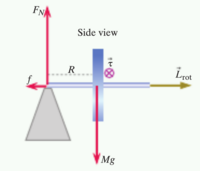
Since the rotor is processing about the support, there must be a perpendicular force f exerted by the support such that ΩP = f, where P is equal to M(Ωr). Thus, f = Mr[math]\displaystyle{ Ω^2 }[/math].
There is also a translational angular momentum of the rotor processing about the support. This can be modeled by finding the magnitude of the position vector crossed with the momentum.
[math]\displaystyle{ L_{support} }[/math] = |R x P |
Since the direction of the rotational angular momentum of the rotor around the support is constantly changing direction, the rate of change of the rotational angular momentum can be written as:
[math]\displaystyle{ L_{rot}Ω }[/math]
Thus the only remaining element that is needed to complete the Angular Momentum Principle is the torque. The torque is equal to the distance from the support to the center of mass of the rotor, r, multiplied by the force exerted, which is the mass times gravity. Therefore, since the change in rotational angular momentum is LrotΩ, that must be equal to τCM. By setting the two equations equal to each other, the angular momentum can be isolated to one side. This yields the following result:
[math]\displaystyle{ \Omega = \frac{\tau CM}{L_{rot}} = \frac{rMg}{I \omega} }[/math]
Real World Examples
Magnetic Resonance Imaging
A good analogy for the way that a Magnetic Resonance Imaging (MRI) works is a gyroscope. To start off with a little background, the way that an MRI works is that all the hydrogen atoms in your body are aligned by using strong magnetic fields. Once these hydrogen atoms are aligned, similar to how a compass's needle is aligned, radio waves can be sent into the body and signals are created from the way the photons emit the radio waves.
Identical to gyroscopes, the hydrogen nucleus rotates about its own axis at a particular frequency. The strength and direction of the magnetic field can effect the direction and angular speed of these rotating protons in the nuclei. By controlling the direction and rotation speed, the location of the hydrogen nucleus can be deduced and thus helping the process of creating images.
Aviation
Gyroscopes are very well understood and applied in aviation. The flight characteristics of airplanes and helicopters are both affected by gyroscopes. Some flight instruments even harness the power of gyroscopes as an integral part of their functionality.
Many airplanes have a propeller mounted on the front of it. This spinning mass on the front of the airplane is a gyroscope! In fact, pilots learn of the gyroscopic precession produced by the propeller when they are learning to take off.
In traditional tail wheel airplanes, the first step during take off is to raise the tail off of the ground and continue down the runway on the main(front) tires. When you rotate the plane and lift the tail off of the ground, you are applying a couple to the whole airplane about its lateral axis. You have a force acting forward on the top of the propeller, and you have a force acting towards the tail on the bottom of the propeller. Since the propeller is a gyroscope, these forces are applied 90 degrees later in the rotation of the propeller. From the pilots seat, the propeller rotates clockwise. Therefore, the forward force that was applied on the top of the propeller, is now applied as a forward force on the right side of the airplane. The rearward force that was applied on the bottom of the propeller is now applied to the left side of the airplane. These two forces create a couple about the vertical axis of the airplane. This couple causes the airplane to yaw (turn) turn to the left when the tail is lifted off the ground. To avoid going off the runway during this time, the pilot must step on the right rudder, keeping the nose of the airplane straight down the runway.
There are three main instruments that use gyroscopes as their source of information, the attitude indicator and the turn coordinator. The attitude indicator uses a gyroscope that is aligned with the horizon. This gyroscope is mounted on a three axis gimbal, so it stays parallel with the horizon. The gyroscope then represents an ‘artificial horizon’ which is very useful for pilots flying in the clouds. Pilots can then, instantaneously determine the pitch and bank of the aircraft. Without this instrument, it is very easy for pilots to get spatially disoriented and not know which way is up or down. Pilots are trained to trust their instruments because the human body is simply not reliable for being spatially aware without a visual reference.
The second gyroscopic instrument is called a heading indicator. This gyroscope spins vertically and is free to rotate about the vertical axis. The gyroscope is aligned facing north upon the start of the airplanes avionics system. When the airplane turns, the gyroscope still points north. This is useful for a pilot to know which direction he is pointed. It is more reliable and accurate than a magnetic compass. (Magnetic compasses have errors when the plane is turning or accelerating because they are not weighted symmetrically.)
The third gyroscopic instrument is called a turn coordinator. The gyroscope is similar to the heading indicator, only the axis of rotation of the gyroscope is not vertical, it is about thirty degrees forward from vertical. When the airplane is turning directions, the gyroscope indicates that the plane is changing directions. This is useful for pilots to do “standard rate turns.” A standard rate turn is three degrees per second. Pilots know if they are doing the standard rate or not based on the turn coordinator.
Control input for helicopters is determined by gyroscopic precession. In order to move in any direction, the force on the main rotor has to be applied 90 degrees earlier in rotation of the rotor. For instance, if you want to go forward, you have to apply a force on the left side of the helicopter.
Without understanding the effects of gyroscopic precession, helicopters wouldn't fly and planes would crash.
Problems
Simple
Problem: Two gyroscopes are made exactly alike except that the spinning disk in one is made of low-density aluminum, whereas the disk in the other is made of high-density lead. If they have the same spin angular speeds and the same torque is applied to both, which gyroscope precesses faster?
Answer:
Precession Angular Speed: [math]\displaystyle{ Ω = \frac{\tau_{cm}}{I\omega} }[/math]
Given:
[math]\displaystyle{ \tau_{Aluminum} = \tau_{Lead} }[/math]
[math]\displaystyle{ \omega_{Aluminum} = \omega_{Lead} }[/math]
Moment of inertia is the remaining variable that can tell us the difference in precession angular speed between the two gyroscopes
Because density is directly proportional to mass and mass is directly proportional to the moment of Inertia, increasing the density would increase the moment of inertia.
Therefore, the spinning disk made of aluminum would precess faster.
Middling
Problem: The axis of a gyroscope is tilted at an angle of 30° to the vertical. The rotor has a radius of 15 cm, mass 3 kg, moment of inertia 0.06 kg·m2, and spins on its axis at 30 rad/s. It is supported in a cage (not shown) in such a way that without an added weight it does not precess. Then a mass of 0.2 kg is hung from the axis at a distance of 18 cm from the center of the rotor.
How long does it take for the gyroscope to make one complete precession?
Answer:
[math]\displaystyle{ Ω = \frac{\tau_{cm}}{L_{rot}} }[/math]
[math]\displaystyle{ L_{rot} = I\omega }[/math]
[math]\displaystyle{ L_{rot} = (0.06 kg * m^2)(30 rad/s) }[/math]
[math]\displaystyle{ = 1.8 kg*m^2*s^-1 }[/math]
We must now consider the torque that is caused by the weight in the y direction
[math]\displaystyle{ \tau_{cm} = mgrsin(30) }[/math]
[math]\displaystyle{ = (0.2 kg) (9.8 m/s^2)(0.18 m)sin(30) }[/math]
[math]\displaystyle{ = 0.1764 kg*m^2 }[/math]
Now, we can calculate the angular speed of precession
[math]\displaystyle{ Ω = \frac{0.1764 kg*m^2}{1.8 kg*m^2*s^-1} }[/math]
[math]\displaystyle{ = 0.098 rad*s^-1 }[/math]
[math]\displaystyle{ t = \frac{2\pi}{ Ω } }[/math]
[math]\displaystyle{ = \frac{2\pi}{0.098 rad*s^-1 } }[/math]
[math]\displaystyle{ = 64 seconds }[/math]
Connectedness
This topic is interesting because gyroscopes have held the fascination of pretty much anyone that has ever seen one in motion including myself. Although the explanation that I gave was a simplified version of a gyroscope which only processes and doesn't nutate, there are many other complex mathematical models of the complicated motion of gyroscopes. Many papers and even books have been written on the subject of gyroscopes, and they have baffled nobel prize winners such as Niels Bohr and famous physicists alike. Gyroscopes are connected to my major because they are huge in industrial manufacturing of numerous materials. We use some sort of gyroscope in our everyday lives from cars to airplanes and other mechanical equipments. At their core, gyroscopes are responsible for measuring or maintaining rotational motion, and it is obvious to see how this would be related to aviation, industrial applications, manufacturing, and vehicle development.
History
Gyroscopes have been around for nearly 200 years. The first person to discover the gyroscope was Johann Bohnenberger in 1817 at the University of Tubingen. However, Bohnenberger was not credited with the discovery of the gyroscope. The French scientist Jean Bernard Leon Foucault (1826-1864) coined the term "gyroscope" and ended up with being credited for the discovery of a gyroscope. Thanks to his experiments with the gyroscope, they started to become mainstream and studied by many other physicists. In the early 20th century, gyroscopes were first used in boats and eventually in aircraft. Gyroscopes have been modified and tweaked to suit many purposes that are widely used today mainly as stabilizers.
See also
Further reading
Compass and Gyroscope: Integrating Science and Politics for the Environment
Mathematical model for gyroscope effects: http://scitation.aip.org/content/aip/proceeding/aipcp/10.1063/1.4915651
YouTube video on gyroscope procession: https://www.youtube.com/watch?v=ty9QSiVC2g0
Wikipedia: https://en.wikipedia.org/wiki/Gyroscope
External links
https://www.youtube.com/watch?v=ty9QSiVC2g0
http://dictionary.reference.com/browse/precession
http://dictionary.reference.com/browse/nutation
https://en.wikipedia.org/wiki/Gyroscope
References
Oxford Dictionaries: http://www.oxforddictionaries.com/us/definition/american_english/gyroscope
HyperPhysics: http://hyperphysics.phy-astr.gsu.edu/hbase/gyr.html
Wikipedia: https://en.wikipedia.org/wiki/Gyroscope
Gyroscope History: http://www.gyroscopes.org/history.asp
Science Learning: http://sciencelearn.org.nz/Contexts/See-through-Body/Sci-Media/Video/So-how-does-MRI-work
Quora: https://www.quora.com/What-the-function-of-gyroscopes-in-airplane
