Faraday's Law
Claimed by Lily Wall Fall 2025
Faraday's Law
focuses on how a time-varying magnetic field produces a "curly" non-Coulomb electric field, thereby inducing an emf.
Faraday's Law
Faraday's Law summarizes the ways voltage can be generated as a result of a time-varying magnetic flux. And it gives a way to connect the magnetic and electric fields in a quantifiable way (will elaborate later). Faraday's law is one of four laws in Maxwell's equations. It tells us that in the presence of a time-varying magnetic field or current (which induces a time-varying magnetic field), there is an emf with a magnitude equal to the change in magnetic flux. It serves as a succinct summary of the ways a voltage (or emf) may be generated by a changing magnetic environment. The induced emf in a coil is equal to the negative of the rate of change of magnetic flux times the number of turns in the coil. It involves the interaction of charge with the magnetic field.
Faraday’s experiments demonstrated that the induced emf from a changing magnetic flux depends on a few key factors. First, the emf is directly proportional to the change in magnetic flux, ΔΦ. Second, the emf increases as the time interval Δt over which the change occurs decreases—in other words, it is inversely proportional to Δt. Lastly, if the coil has N turns, the resulting emf is N times greater than that of a single loop, making emf directly proportional to N.
Curly Electric Field

Mathematical Model
Faraday's Law
emf = [math]\displaystyle{ {\frac{-d{{Phi}}_{mag}}{dt}} }[/math]
where emf = [math]\displaystyle{ \oint\vec{E}_{NC}\bullet d\vec{l} }[/math] and [math]\displaystyle{ {{Phi}}_{mag}\equiv\int\vec{B}\bullet\hat{n}dA }[/math]
In other words: The emf along a round-trip is equal to the rate of change of the magnetic flux on the area encircled by the path.
Direction: With the thumb of your right hand pointing in the direction of the -dB/dt, your fingers curl around in the direction of Enc.
The meaning of the minus sign: If the thumb of your right hand points in the direction of -dB/dt (that is, the opposite of the direction in which the magnetic field is increasing), your fingers curl around in the direction along which the path integral of electric field is positive. Similarly, the direction of the induced current can be explained using Lenz's Law. Lenz's law states that the induced current from the non-Coulombic electric field is induced in such a way that it produces a magnetic field that opposes the first magnetic field to keep the magnetic flux constant.
Formal Version of Faraday's Law
[math]\displaystyle{ \oint\vec{E}_{NC}\bullet d\vec{l} = {\frac{-d}{dt}}\int\vec{B}\bullet\hat{n}dA }[/math] (sign given by right-hand rule)
Fiding the direction of the induced conventional current
To find the direction of the induced conventional current by the change in the magnetic flux one must find the direction of the Non-Coulomb electric filed generated by the change in flux as the conventional current is the direction of the Non-Coulomb electric field. To find the direction of the the Non-Coulomb Electic field, one must find the direction of [math]\displaystyle{ \frac{-dB}{dt} }[/math]. Do this using the change in magnetic field as the basis of finding the [math]\displaystyle{ \frac{-dB}{dt} }[/math].
As stated previously the negative sign in front of the change in magnetic flux in the Law is a representative of Lenz's law or in other words, it's there to remind us to apply Lenz's law. Lenz's law is basically there to make us abide by the law of conservation of energy. That said, thinking in terms of conservation of energy provides the simplest way to figure out the direction of the Non-Coulomb electric field. The external magnetic field induces the Non-Coulomb electric field which drives the current which in turn creates a new magnetic field which we will call the induced magnetic field. This is the magnetic field whose direction we can deduce which in turn will help us find the direction of the current. The easiest way to do this is to imagine a loop of wire with and an external magnetic field perpendicular to the surface of the plane of the loop. There is a change in magnetic flux generated by the change in the magnitude of the magnetic field. vector for the initial external magnetic field and a vector for the final magnetic field. Then, draw the change in magnetic field vector, [math]\displaystyle{ \Delta \mathbf{B} }[/math], and then the negative vector of that change in magnetic field gives [math]\displaystyle{ \frac{-dB}{dt} }[/math]:


Pointing the thumb of your right hand in the direction of [math]\displaystyle{ \frac{-dB}{dt} }[/math] allows you to curl your fingers in the direction of [math]\displaystyle{ \mathbf{E_{NC}} }[/math].
The negative sign in Faraday’s law expresses Lenz’s law: nature resists sudden changes in flux.
- If the magnetic field through a loop increases, the induced current produces a field that reduces it.
- If the magnetic field decreases, the induced current produces a field that increases it.
This opposition maintains consistency with energy conservation.
In this chapter we have seen that a changing magnetic flux induces an emf:

according to Faraday’s law of induction. For a conductor which forms a closed loop, the emf sets up an induced current I =|ε|/R , where R is the resistance of the loop. To compute the induced current and its direction, we follow the procedure below:
1. For the closed loop of area on a plane, define an area vector A and let it point in the direction of your thumb, for the convenience of applying the right-hand rule later. Compute the magnetic flux through the loop using

Determine the sign of the magnetic flux ![]()
2. Evaluate the rate of change of magnetic flux ![]() . Keep in mind that the change
could be caused by
. Keep in mind that the change
could be caused by

Determine the sign of ![]()
3. The sign of the induced emf is the opposite of that of ![]() . The direction of the
induced current can be found by using Lenz’s law or right-hand rule (discussed previously).
. The direction of the
induced current can be found by using Lenz’s law or right-hand rule (discussed previously).
Coulomb vs. non-Coulomb Electric Fields
Coulomb and Non-Coulomb electric fields may look similar, but they arise from entirely different causes. Coulomb fields come from electric charges and can be described by an electric potential. Non-Coulomb fields are created by changing magnetic flux, form closed loops, and cannot be written as a potential. Telling these two apart is key to understanding why induced currents behave the way they do in Faraday’s law.
| Type of Electric Field | Coulomb Field | Non-Coulomb Field |
|---|---|---|
| Source | Electric charges (positive or negative) | Changing magnetic flux (Faraday’s law) |
| Field Lines | Begin and end on charges
(point outward from +, inward to –) |
Form closed loops; have no beginning or end |
| Conservative? | Yes — circulation around any closed loop is zero | No — circulation is non-zero (induces EMF) |
| Can it be written as an electric potential gradient [math]\displaystyle{ \nabla V }[/math]? | Yes | No |
| Physical Interpretation | Electric force from static charges | Induced electric field that resists changes in flux (Lenz’s law) |
| Typical Examples | Charged spheres, point charges, capacitor plates | Electric generator coils, induction cooktops, moving magnets |
Computational Model of Faraday's Law
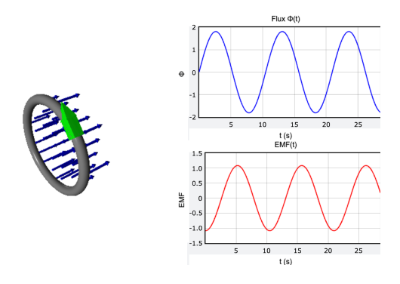
To help visualize how a time-varying magnetic field induces an emf, here is a fully interactive GlowScript simulation. The model shows a loop of wire with a magnetic field that oscillates in time, producing a changing magnetic flux. According to Faraday’s law, this changing flux induces a non-Coulomb electric field which drives a circulating current in the loop.
You can open and run the simulation using the link below:
Faraday’s Law Interactive Simulation
The visualization includes:
- A loop of wire representing the conducting circuit
- Many small arrows showing the magnetic field through the loop area
- A time-varying magnetic field [math]\displaystyle{ B(t) }[/math]
- Flux [math]\displaystyle{ \Phi(t) }[/math] and induced emf [math]\displaystyle{ \mathcal{E}(t) }[/math] graphs
- A rotating arrow showing the direction of the induced current according to Lenz’s law
From the graphs, you can clearly see that the emf curve is the negative time derivative of the flux curve, matching the relationship [math]\displaystyle{ \mathcal{E}(t) = -\,\frac{d\Phi(t)}{dt} }[/math] in Faraday’s law.
This model provides a clear, dynamic illustration of how a changing magnetic field induces an emf in a loop.
More on Faraday's Law
Moving a magnet near a coil is not the only way to induce an emf in the coil. Another way to induce emf in a coil is to bring another coil with a steady current near the first coil, thereby changing the magnetic field (and flux) surrounding the first coil, inducing an emf and a current. Also, rotating a bar magnet (or coil) near a coil produces a time-varying magnetic field in the coil since rotating the magnet changes the magnetic field in the coil. The key to inducing the emf in the second coil is to change the magnetic field around it somehow, either by bringing an object that has its own magnetic field around that coil, or changing the current in that object, changing its magnetic field.
Faraday's law can be used to calculate motional emf as well. A bar on two current-carrying rails connected by a resistor moves along the rails, using a magnetic force to induce a current in the wire. There is a magnetic field going into the page. One way to calculate the motional emf is to use the magnetic force, but an easier way is to use Faraday's law.
Faraday's law, using the change in magnetic flux, can be used to find the motional emf, where the changing factor in the magnetic flux is the area of the circuit as the bar moves, while the magnetic field is kept constant.

Examples
Simple

Adapted from the Matter & Interactions textbook, variation of P12 (4th ed).
The solenoid radius is 4 cm and the ring radius is 20 cm. B = 0.8 T inside the solenoid and approximately 0 outside the solenoid. What is the magnetic flux through the outer ring?
Solution:
Because the magnetic field outside the solenoid is 0, there is no flux between the ring and solenoid. So the flux in the ring is due to the area of the solenoid, so we use the area of the solenoid to find the flux through the outer ring rather than the area of the ring itself:
[math]\displaystyle{ \phi = BAcos(\theta) }[/math]
[math]\displaystyle{ = (0.8 T)(\pi)(0.04 m)^2cos(0) }[/math]
[math]\displaystyle{ = 4.02 x 10^{-3} T*m^2 }[/math]
Middle

Adapted from the Matter & Interactions textbook, variation of P27 (4th ed).
A very long, tightly wound solenoid has a circular cross-section of radius 2 cm (only a portion of the very long solenoid is shown). The magnetic field outside the solenoid is negligible. Throughout the inside of the solenoid the magnetic field B is uniform, to the left as shown, but varying with time t: B = (.06+.02[math]\displaystyle{ t^2 }[/math])T. Surrounding the circular solenoid is a loop of 7 turns of wire in the shape of a rectangle 6 cm by 12 cm. The total resistance of the 7-turn loop is 0.2 ohms.
(a) At t = 2 s, what is the direction of the current in the 7-turn loop? Explain briefly.
(b) At t = 2 s, what is the magnitude of the current in the 7-turn loop? Explain briefly.
Solution
(a) The direction of the current in the loop is clockwise.
(b)
B(t) = (.06+.02[math]\displaystyle{ t^2 }[/math])
A = (π)(0.02 m)^2 = .00126 [math]\displaystyle{ m^2 }[/math]
[math]\displaystyle{ |{ε}| = AN\frac{dB(t)}{dt} }[/math]
[math]\displaystyle{ |{ε}| }[/math] = (.00126 [math]\displaystyle{ m^2 }[/math])(7)[math]\displaystyle{ \frac{d(.06+.02t^2)}{dt} }[/math] = (.00882)(.02)(2t) = .0003528t
At t = 2 s:
[math]\displaystyle{ |{ε}| }[/math] = .0003528(2) = .0007056 V
[math]\displaystyle{ i = \frac{{ε}}{R} }[/math]
[math]\displaystyle{ i = \frac{{.0007056 V}}{0.2 ohms} }[/math] = .00353 A
Difficult

A square loop (dimensions L⇥L, total resistance R) is located halfway inside a region with uniform magnetic field B0. The magnitude of the magnetic field suddenly begins to increase linearly in time, eventually quadrupling in a time T.
(a) What current (magnitude and direction), if any, is induced in the loop at time T?
[math]\displaystyle{ |emf| = \frac{-{Φ}_{B}}{Δt} = \frac{A(B_f - B_i)}{T} = \frac{L^2(4B_o - B_o)}{T} = \frac{3B_oL^2}{T} }[/math]
emf = IR = [math]\displaystyle{ \frac{3B_oL^2}{TR} }[/math]
(b) What net force (magnitude and direction), if any, is induced on the loop at time T?
[math]\displaystyle{ F_{top} }[/math] and [math]\displaystyle{ F_{bottom} }[/math] cancel out. [math]\displaystyle{ F_{left} }[/math] = 0 because the left side is out of [math]\displaystyle{ \vec{B} }[/math] region.
[math]\displaystyle{ \vec{F} }[/math] = [math]\displaystyle{ \vec{F}_{right} }[/math] = I [math]\displaystyle{ \vec{L} \times \vec{B} = (ILB)[(\hat{y} \times - \hat{z} )] = \frac{3B_oL^2}{TR}(4B_o L)(- \hat{x}) = \frac{3{B_o}^2 L^3}{TR}(- \hat{x}) }[/math]
(c) What net torque (magnitude and direction), if any, is induced on the loop at time T?
[math]\displaystyle{ \vec{τ} = \vec{μ} \times \vec{B} = 0 }[/math] because [math]\displaystyle{ \vec{μ} }[/math] and [math]\displaystyle{ \vec{B} }[/math] are anti-parallel.
Connectedness
Faraday's Law is one of Maxwell's equations which describe the essence of electric and magnetic fields. Maxwell's equations effectively summarize and connect all that we have learned throughout the course of Physics 2.
As an electrical engineer, Faraday's Law is relevant to my major.
Faraday’s Law Applications
Generators
The most common application of Faraday's Law is in the generation of electricity. Most power plants rely on Faraday's Law to convert mechanical energy (whether it be hydroelectric, nuclear, thermal, etc) into electrical energy. A generator contains a coil of wire, called an armature, and a magnet. As the armature rotates within the magnetic field, the changing magnetic flux produces an induced emf, just as described in Faraday's Law. This electric current can now be used to power electronics such as lights, appliances, and electronic devices.
Transformers
Transformers are used to increase or decrease the voltage of an electric current, and are created using the principles of Faraday's Law. Transformers can be found in an assortment of items such as power adapters for phones, microwaves, stoves, and other electrical items. A transformer consists of two coils: one coil, called the primary coil, has an alternating voltage connected to it (an AC circuit), which therefore generates a rate of change of flux. The other coil, called the secondary coil, experiences this rate of change of flux and therefore has an induced emf which is consistent with Faraday's Law. When the secondary coil is connected to a circuit, it results in an induced current. The primary and secondary coils have a different number of turns between the two, which results in the output voltage being different than the input voltage. Depending on which coil has more or less turns, the input voltage will be transformed into a higher or lower output voltage.
Hydroelectric Generators
Generators create energy by transforming mechanical motion into electrical energy, but hydroelectric generators use the power of falling water to turn a large turbine which is connected to a large magnet. Around this magnet is a large coil of tightly wound wire. The conceptual creation of electricity is the same as Faraday’s Law except alternating current is being produced, but the idea that a changing magnetic field in a coil of wire induces an electromotive force is still the same. The difference is the magnetic field changes sign and flips resulting in the same thing to occur in the induced EMF. Although the calculations here are slightly more difficult the concepts are the same.
Transformers
Transformers use a similar concept for Faraday’s Law but it’s slightly different. The job of a transformer is to either step up or step down the voltage on the power line. Transformers have a constant magnetic field associated with it due to an iron core. The power supply voltage is adjusted by altering the number of turns of wire around the iron core which in turn alters the EMF of the electricity.
Cartoon of Hydroelectric Plant
https://etrical.files.wordpress.com/2009/12/hydrohow.jpg
Turbine Picture
http://theprepperpodcast.com/wp-content/uploads/2016/02/108-All-About-Hydro-Power-Generators-1054x500.jpg
Transformer Diagram https://en.wikipedia.org/wiki/Transformer#/media/File:Transformer3d_col3.svg
History
In 1831, eletromagnetic induction was discovered by Michael Faraday.
Faraday's Law Experiment

Faraday showed that no current is registered in the galvanometer when bar magnet is stationary with respect to the loop. However, a current is induced in the loop when a relative motion exists between the bar magnet and the loop. In particular, the galvanometer deflects in one direction as the magnet approaches the loop, and the opposite direction as it moves away.
Faraday’s experiment demonstrates that an electric current is induced in the loop by changing the magnetic field. The coil behaves as if it were connected to an emf source. Experimentally it is found that the induced emf depends on the rate of change of magnetic flux through the coil.
Test it out yourself here
See also
Further Readings
Matter and Interactions, Volume II: Electric and Magnetic Interactions, 4th Edition
The Electric Life of Michael Faraday (2009) by Alan Hirshfield
Electromagnetic Induction Phenomena (2012) by D. Schieber
External Links
https://www.youtube.com/watch?v=KGTZPTnZBFE
https://www.nde-ed.org/EducationResources/HighSchool/Electricity/electroinduction.htm
http://www.famousscientists.org/michael-faraday/
http://www.bbc.co.uk/history/historic_figures/faraday_michael.shtml
References
Matter and Interactions, 4th Edition
http://hyperphysics.phy-astr.gsu.edu/hbase/electric/farlaw.html
https://en.wikipedia.org/wiki/Faraday%27s_law_of_induction
https://openstax.org/books/college-physics-2e/pages/23-2-faradays-law-of-induction-lenzs-law