Charged Capacitor
The Main Idea
A capacitor is when two uniformly, but oppositely (-Q and +Q), charged metal plates are held very close to each other with a separation of s which stores electric charge. The effect of a capacitor is capacitance, which represents how an electric charge changes with respect to the electric potential.
This page is dedicated to understanding and calculating the electric field of a capacitor through definition, mathematical models, computational models, and example problems.
A Mathematical Model
The mathematical model to the electric field of a charged capacitor (near the center of the capacitor) is [math]\displaystyle{ E \approx {\frac{Q/A}{{\epsilon}_0}} }[/math], where Q is the magnitude of the plate charges and A is the area of each plates. The direction is perpendicular to the plates.
The fringe field (field located near the center of the disks but right outside of the plates) is [math]\displaystyle{ E_{fringe} \approx {\frac{Q/A}{2{\epsilon}_0}} (\frac{s}{R}) }[/math]
Derivation
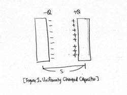
Take the origin at the surface of the left plane, with the z-axis running to the right. We assume that each disk has a uniformly charge density (s [math]\displaystyle{ \ll }[/math] R).
Then, the contribution of the negative capacitor is [math]\displaystyle{ E_- \approx {\frac{Q/A}{2{\epsilon}_0}} [1-\frac{z}{R}] }[/math] (to the left) and the positive capacitor is [math]\displaystyle{ E_+ \approx {\frac{Q/A}{2{\epsilon}_0}} [1-\frac{s-z}{R}] }[/math] (to the left).
If we add up the contributions, [math]\displaystyle{ E_{total} \approx {\frac{Q/A}{2{\epsilon}_0}} [1-\frac{z}{R}] + {\frac{Q/A}{2{\epsilon}_0}} [1-\frac{s-z}{R}] \approx {\frac{Q/A}{{\epsilon}_0}} [1-\frac{s/2}{R}] }[/math]. Since s [math]\displaystyle{ \ll }[/math] R, [math]\displaystyle{ E \approx {\frac{Q/A}{{\epsilon}_0}} }[/math].
Gauss's Law
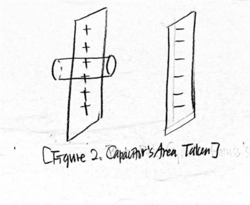
Say [math]\displaystyle{ \sigma }[/math] is the surface charge density, and the area on each side of the cylinder is A.
Since Gauss's Law is [math]\displaystyle{ \Phi = \lmoustache \vec{E} \cdot d\vec{A} }[/math], [math]\displaystyle{ \Phi_{left} }[/math] = 0, [math]\displaystyle{ \Phi_{circular sides} }[/math] = 0, and [math]\displaystyle{ \Phi_{right} = \frac{Q_{enclosed}}{\varepsilon_0} }[/math]; while [math]\displaystyle{ \vec{E}_{left} = 0 }[/math], [math]\displaystyle{ \vec{E}_{circular sides} \perp \vec{A} }[/math].
Thus, EA = [math]\displaystyle{ \Phi = \lmoustache \vec{E} \cdot d\vec{A} }[/math] = [math]\displaystyle{ \Phi_{right} = \frac{Q_{enclosed}}{\varepsilon_0} }[/math] = [math]\displaystyle{ \frac{\sigma A}{\varepsilon_0} }[/math]. Therefore, E = [math]\displaystyle{ \frac{\sigma}{\varepsilon_0} }[/math]
A Computational Model
Uniformly charged capacitors can be further explored through PhET Interactive Simulations. Here, the user can explore how a capacitor works by changing the size of capacitors and add different objects such as dielectrics to observe how they affect capacitance.
Charged capacitors can also be visualized through this vpython code created on the website Teach hands-on with GlowScript
Examples
Simple
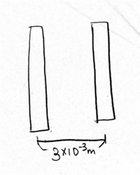
If the plate separation, s, for a capacitor is [math]\displaystyle{ 3 \times 10^{-3} }[/math]m, determine the area of the plates if the capacitance is 3 F.
Since [math]\displaystyle{ C = \frac{\varepsilon_{0}A}{d} }[/math],
[math]\displaystyle{ A = \frac{Cd}{\varepsilon_{0}} }[/math]
[math]\displaystyle{ A = \frac{3 F\times (3\times10^{-3}) m}{8.85\times10^{-12}C^2 N^{-1} m^{-2}} }[/math] = [math]\displaystyle{ 1.02\times10^{9} m^2 }[/math].
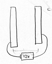
Determine the amount of charged on one side of a capacitor with the capacitance of [math]\displaystyle{ 2\times10^{-6} F }[/math] when the capacitor is connected to a 12 V battery.
Since [math]\displaystyle{ C = \frac{Q}{V} }[/math],
[math]\displaystyle{ Q = C \times V }[/math]
[math]\displaystyle{ Q = (2\times10^{-6} F\times12 V) = 2.4\times10^{-5} C }[/math].
Middling
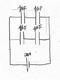
Evaluate the circuit and determine the effective capacitance and charge and voltage across each capacitor.
The capacitors are connected in series in the top and bottom row, so in each row, the total capacitance is [math]\displaystyle{ \frac{1}{4\mu} F + \frac{1}{4\mu} F = 2\mu }[/math] F. The two rows are connected in parallel, so thus, the effective capacitance is [math]\displaystyle{ 2\mu F + 2\mu F = 4\mu }[/math] F.
To find the charge on each of the 2[math]\displaystyle{ \mu }[/math] F capacitor, the equation [math]\displaystyle{ C = \frac{Q}{V} }[/math] is used.
Since [math]\displaystyle{ C = \frac{Q}{V} }[/math],
[math]\displaystyle{ Q = C \times V = 2\mu F\times 20 V = 40\mu C }[/math]
To find the voltage on each rows containing the two 4[math]\displaystyle{ \mu }[/math] F capacitor,
Since [math]\displaystyle{ C = \frac{Q}{V} }[/math],
[math]\displaystyle{ V = \frac{Q}{C} = \frac{40 \mu\frac{C}{V}}{2\mu F} }[/math] = 10 V.
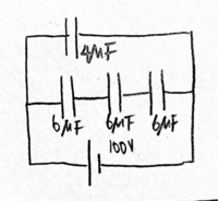
Evaluate the circuit and determine the effective capacitance and charge and voltage across each capacitor.
Since all three capacitors are connected in series in the bottom row, the bottom row's total capacitance will be [math]\displaystyle{ \frac{1}{6\mu} F + \frac{1}{6\mu} F + \frac{1}{6\mu} F = 2\mu }[/math] F. The top row and the bottom row are connected in parallel, so the effective capacitance is [math]\displaystyle{ 4\mu F + 2\mu F = 6\mu F }[/math].
Since [math]\displaystyle{ C = \frac{Q}{V} }[/math],
the charge across the [math]\displaystyle{ 4\mu }[/math] F capacitor is [math]\displaystyle{ Q = C \times V = 4\mu F\times 100 V = 400 \mu C }[/math],
and the charge across the row containing the three [math]\displaystyle{ 6\mu }[/math] capacitors is [math]\displaystyle{ Q = C \times V = 2\mu F\times 100 V = 200 \mu C }[/math].
The voltage across the [math]\displaystyle{ 6\mu }[/math] capacitor is [math]\displaystyle{ V = \frac{Q}{C} = \frac{200\mu C}{6\mu F} = 33.3 V }[/math]
Difficult
A proton traveling in the -x direction approaches a capacitor consisting of two large, oppositely charged plates. The circular plates are 0.04 m apart, and each has a radius of 1.7 m. The proton enters the capacitor through a small hole in location A at the right side of plates at [math]\displaystyle{ 2.5 \times 10^{4} \frac{m}{s} }[/math] and exists through the hole at location B with a speed of [math]\displaystyle{ 7.9 \times 10^{4} \frac{m}{s} }[/math].
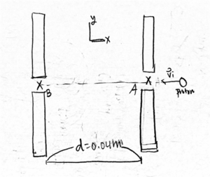
First, we have to find the potential difference between B and A [math]\displaystyle{ (V_B - V_A) }[/math].
Since this is a closed system, [math]\displaystyle{ \Delta K + \Delta U = 0 }[/math]. Then,
[math]\displaystyle{ \Delta U = -\Delta K = -\frac{1}{2} m ({v_f}^2 - {v_i}^2) = -\frac{1}{2} (1.7e-27)[{7.9e4}^2 - {2.5e4}^2] = -4.77e-18 J }[/math]
[math]\displaystyle{ \Delta U = q\Delta V \Leftrightarrow \Delta V = \frac{1}{q} \Delta U = \frac{-4.77e-18 J}{1.6e-19 C} = -29.8 \frac{J}{C} }[/math].
Since [math]\displaystyle{ E_{capacitor} = \frac{Q/A}{\varepsilon_0} = \frac{Q}{\pi R^2 \varepsilon_0} }[/math], and for a uniform electric field, \Delta V = Ed[math]\displaystyle{ }[/math],
[math]\displaystyle{ \Delta V = \frac{Q}{\pi R^2 \varepsilon_0} \Leftrightarrow Q = \frac{\Delta V \pi R^2 \varepsilon_0}{d} = \frac{29.8 V \pi ({1.7}^2 m^2) (8.85e-12 C^2 N^{-1} m^{-2})}{0.04 m} = 5.99e-8 C }[/math].
Connectedness
(should be completed by a student)
History
(should be completed by a student)
See also
Further reading
Capacitors can also be read in Free Book Centre, where there are free electricity and magnetism books.
External links
Charged capacitors are further explained in websites such as:
[math]\displaystyle{ \bullet }[/math] Hyperphysics
[math]\displaystyle{ \bullet }[/math] Khan Academy
[math]\displaystyle{ \bullet }[/math] Physics.info
References
Chabay, R. W. (2015). Matter and interactions: Electric and magnetic interactions. Wiley.
D. (2013). Gauss' Law Explained and Parallel Plate Capacitor Worked Examples | Doc Physics. Retrieved April 17, 2016, from https://www.youtube.com/watch?v=hnt07JpNE1E
Get Ready. Be Prepared. Understand the Big Ideas. (n.d.). Retrieved April 17, 2016, from http://www.physics-prep.com/index.php/practice-problems-capacitors/43-physics-2-unit-1/1437-practice-problems-capacitance-solutions