Parallel Circuits vs. Series Circuits*: Difference between revisions
Bburnette6 (talk | contribs) No edit summary |
mNo edit summary |
||
| Line 1: | Line 1: | ||
'''Claimed by Christina Zhao Fall 2018''' | |||
'''Claimed by Brandon Burnette Spring 2017''' | '''Claimed by Brandon Burnette Spring 2017''' | ||
Revision as of 16:33, 4 November 2018
Claimed by Christina Zhao Fall 2018 Claimed by Brandon Burnette Spring 2017
Parallel Circuits vs. Series Circuits
In a circuit containing a power source and different electrical elements such as resistors, capacitors, or bulbs, the elements of the circuit can be connected either in parallel or in series, relative to the power source. Each type of connection affects the resistivity and overall current in the circuit. These different circuits have different laws for calculating current, voltage, and resistance through the circuit.
Suppose we have three bulbs and a battery to connect together in a circuit.
One way to connect the bulbs is connect them in line with the battery, in such a way that a charge traveling from the high potential end of the battery to its low potential end would have to travel through all three bulbs to get to there. These bulbs are connected in series. However, in connecting our circuit this way we will experience a voltage drop and a corresponding brightness drop through the bulbs. This is less than ideal for something such as house wiring.
Another way to connect the bulbs is to make them branch off from a common point connected to the high potential of the battery, creating three paths to go from one end of the battery to the other. A charge traveling from the high potential end of the battery to the low potential end would only travel through one of the three branches, and therefore through one of the three bulbs. These bulbs are connected in parallel. These circuits will have less of a current going through each bulb, yet each voltage will have the same amount of current going through them.
A Mathematical Model
A ohmic circuit is a set of resistors linked together in an unique combination. It can also includes components such as bulbs, heaters and meters as long as they can be considered ohmic. In other words, if all components in a circuit only release heat when connected to a power source like battery, then the circuit is ohmic, and such a circuit is easy to analyze when components are connected in parallel or in series by using Ohm's law. We may need to use other laws when analyzing non-ohmic circuits. Any resistors may become non-ohmic under very high voltage, and some may be so under low voltage.
A Computational Model
For a purely in-series circuit, (or purely in-series combination of resistors)
[math]\displaystyle{ U_{total}=U_{1}+U_{2}+U_{3}+...+U_{n} }[/math]
[math]\displaystyle{ I_{total}=I_{1}=I_{2}=I_{3}=...=I_{n} }[/math]
[math]\displaystyle{ R_{total} = R_{1} + R_{2} + R_{3} + ... + R_{n} }[/math]
if there are n ohmic components in the circuit connected in series.
For a purely in-parallel circuit, (or purely in-parallel combination of resistors)
[math]\displaystyle{ U_{total} = U_{1} = U_{2} = U_{3} = ... = U_{n} }[/math]
[math]\displaystyle{ I_{total} = I_{1} + I_{2} + I_{3} + ... + I_{n} }[/math]
[math]\displaystyle{ {\frac{1}{R}_{total}} = {\frac{1}{R}_{1}} +{\frac{1}{R}_{2}} + {\frac{1}{R}_{3}} + ... + {\frac{1}{R}_{n}} }[/math]
For ohmic circuits,
When a circuit is analyzed, cut up circuits into purely in-series combination of components or purely in-parallel combination of components, calculate resistance of each combination of components. Reduce the circuit until it is purely in-series or in-parallel and calculate the current, total resistance and potential difference between two ends of each component.
How do I remember this?
In order to tell the difference between parallel and series circuits, I like to think of current as being equivalent to water running through pipes. In a straight line, the same amount of water passes through every part of the pipe. Current behaves the same way. So in series circuit the same current runs through all pieces. However, the parallel circuit is equivalent to a pipe with branches. These branches lead to the current being proportionally split by the size of the branch, just like a circuit in parallel.
Examples
A visual Example
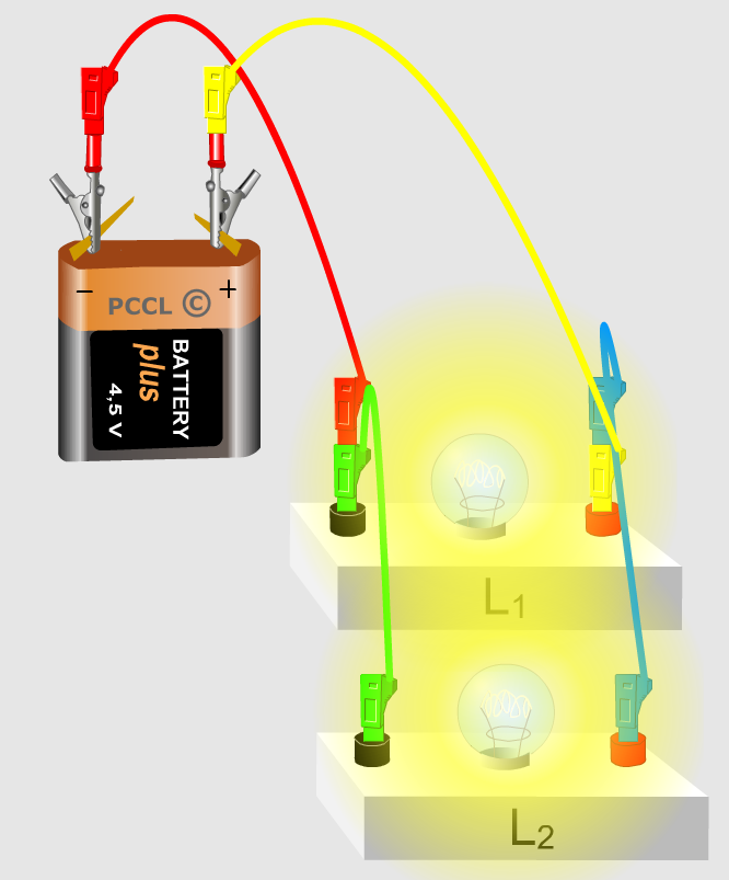
Parallel Circuit
This shows an example of a simple circuit consisting of a battery and two lightbulbs wired in parallel. You will notice that both of the bulbs are bright because the same voltage is going across each of them.Brightness is proportional to voltage, a higher voltage produces a brighter light. In this circuit the lightbulbs are equivalent to a resistor. They have current running through them equal to half the total current and all of the voltage the battery puts out.
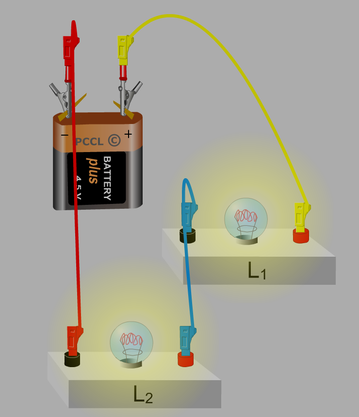
Series Circuit
This shows an example of a simple circuit consisting of a battery and two lightbulbs wired in series. You will notice that both of the bulbs are dim because half of the total voltage is going across each of them.Brightness is proportional to voltage, a higher voltage produces a brighter light. So, the brightness of the first example can not be acheived by this second circuit. In this circuit the lightbulbs are equivalent to a resistor. They have the same amount of current running through each of them.
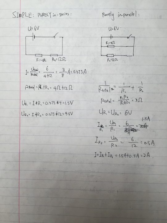
Simple
- Purely in-series:
- Purely in-parallel:
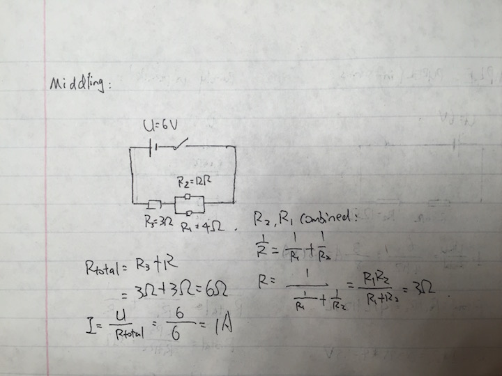
Middling
- simple combination of one in-series component or one in-parallel component:
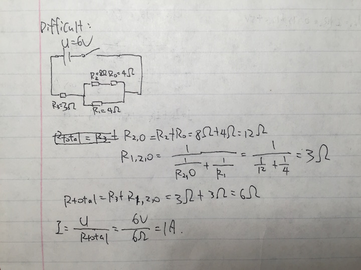
Difficult
- complex combination of in-series and in-parallel components:
Connectedness
How is this topic connected to something that you are interested in?
This topic helps me roughly estimate the amperage, power consumption and heat generation of an circuit, with adaptions. It helps build design a circuit.
How is it connected to your major?
For simple estimation of power supply of an ohmic circuit, we may apply the model to calculate the result.
Is there an interesting industrial application?
Yes. Simply put, daisy-chained computer devices are in-series, while wall plugs in everyone's home are in-parallel. The model helps design them.
History
The fundamental principles of in-series and in-parallel models, ohm's law, an empirical law, was discovered by Georg Ohm, a German scientist, in 1827[1], which states "which states that the current flow through a conductor is directly proportional to the potential difference (voltage) and inversely proportional to the resistance." It has many limitations. It can only be applied to ohmic circuits (circuits which only generate heat). Ohm was not recognized for his achievement until 1849, when he finally got the chair in University of Munich.
See also
Further reading and external links
Books, Articles or other print media on this topic
About Ohm's law: [4]
References
Georg Ohm: 1
