Parallel Circuits vs. Series Circuits*: Difference between revisions
Ivan Peshev (talk | contribs) (Added a new section about delta-Y circuits which was not present before. This method is an application to simplify more complex structures of resistor networks and find equivalent networks through mathematical formulas and calculations. All images are copyright-free and taken as screenshots from an online circuit simulator.) |
|||
| (33 intermediate revisions by 4 users not shown) | |||
| Line 1: | Line 1: | ||
'''Claimed by | '''Claimed by Christina Zhao Fall 2018''' | ||
'''Edited by Ivan Peshev Spring 2023''' | |||
==The Main Idea== | |||
A typical circuit consists of a power source, usually a battery, and electrical elements such as resistors and capacitors. Resistors include light bulbs and do not provide power. Resistors, depending on how they are positioned in a circuit, reduces the voltage or the current that passes through them, and can change the equivalent, or total resistance in a circuit. | |||
Resistors connected in series are attached to the power source in a way that there are no nodes where the current splits. Therefore, according to the node rule, the current flowing through each resistor is the same. However, the voltage drop across each resistor is not equal for every resistor. | |||
If these resistors are light bulbs, they are connected in line with the battery. The relative brightness decreases across each bulb, making series connections not ideal for something such as house wiring. This drop is consistent with the loop rule, which states that around a full loop of a circuit, the potential difference is 0. | |||
[[File:Example_series.PNG]] | |||
Resistors connected in parallel are connected to a power source but are on different branches of wire, meaning that the resistors experience the same potential difference. But, due to being connected to different nodes of the circuit, have different currents flowing across them. The branches of a basic parallel circuit looks like rungs of a ladder. | |||
If these resistors are light bulbs, they are connected from a common point to the potential of the battery and all have the same brightness. | |||
[[File:Example_parallel.PNG]] | |||
===A Mathematical Model=== | |||
An ohmic circuit is a set of resistors linked together in an unique combination. It can also include components such as bulbs, heaters, and meters as long as they can be considered ohmic. As is expected, if all the components obey Ohm's Law V=IR, then it is considered ohmic. Such a circuit is easy to analyze when components are connected in parallel or in series by using Ohm's law. We may need to use other laws when analyzing non-ohmic circuits. Any resistors may become non-ohmic under very high voltage, and some may be so under low voltage. | |||
For a purely in-series circuit, (or purely in-series combination of resistors) | |||
<math>U_{total}=U_{1}+U_{2}+U_{3}+...+U_{n}</math> | |||
=== | <math>I_{total}=I_{1}=I_{2}=I_{3}=...=I_{n}</math> | ||
<math>R_{total} = R_{1} + R_{2} + R_{3} + ... + R_{n}</math> | |||
if there are n ohmic components in the circuit connected in series. | |||
For a purely in-parallel circuit, (or purely in-parallel combination of resistors) | |||
<math>U_{total} = U_{1} = U_{2} = U_{3} = ... = U_{n}</math> | |||
<math>I_{total} = I_{1} + I_{2} + I_{3} + ... + I_{n}</math> | |||
<math>{\frac{1}{R}_{total}} = {\frac{1}{R}_{1}} +{\frac{1}{R}_{2}} + {\frac{1}{R}_{3}} + ... + {\frac{1}{R}_{n}}</math> | |||
When a circuit is analyzed, cut up circuits into purely in-series combination of components or purely in-parallel combination of components, calculate resistance of each combination of components. Reduce the circuit until it is purely in-series or in-parallel and calculate the current, total resistance and potential difference between two ends of each component. | |||
===A Computational Model=== | ===A Computational Model=== | ||
[[File:Parallel circuit2.png|500px]] | |||
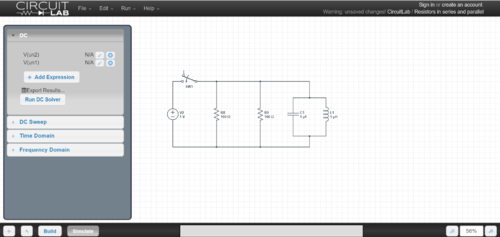
This [https://www.circuitlab.com/circuit/g2qzxs/resistors-in-series-and-parallel/ website] is a schematic builder that can be used to model circuits and test differences in current, voltage, and resistance with with various combinations of parallel and series. | |||
'''Parallel Circuit''' | |||
[[File:ParallelBattery.png]] | |||
http://www.physics-chemistry-interactive-flash-animation.com/electricity_electromagnetism_interactive/components_circuits_association-series_parallel.htm | |||
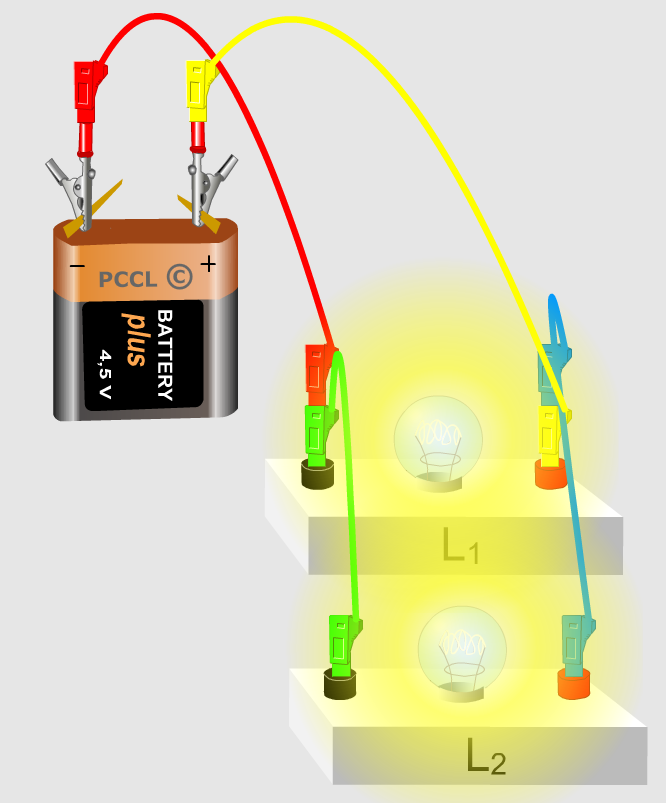
This shows an example of a simple circuit consisting of a battery and two lightbulbs wired in parallel. You will notice that both of the bulbs are bright because the same voltage is going across each of them. Brightness is proportional to voltage, a higher voltage produces a brighter light. In this circuit, the lightbulbs are equivalent to resistors. They have current running through them equal to half the total current and all of the voltage the battery puts out. | |||
'''Series Circuit''' | |||
[[File:SeriesCircuit.png]] | |||
http://www.physics-chemistry-interactive-flash-animation.com/electricity_electromagnetism_interactive/components_circuits_association-series_parallel.htm | |||
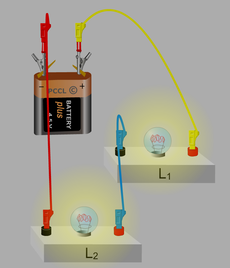
This shows an example of a simple circuit consisting of a battery and two lightbulbs wired in series. You will notice that both of the bulbs are dim because half of the total voltage is going across each of them. Brightness is proportional to voltage, a higher voltage produces a brighter light. So, the brightness of the first example can not be achieved by this second circuit. In this circuit the lightbulbs are equivalent to a resistor. They have the same amount of current running through each of them. | |||
'''How do I remember this?''' | |||
In order to tell the difference between parallel and series circuits, I like to think of current as being equivalent to water running through pipes. In a straight line, the same amount of water passes through every part of the pipe. Current behaves the same way. So in series circuit the same current runs through all pieces. However, the parallel circuit is equivalent to a pipe with branches. These branches lead to the current being proportionally split by the size of the branch, just like a circuit in parallel. | |||
==Examples== | ==Examples== | ||
===Simple=== | |||
'''Question''' | |||
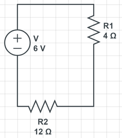
#Purely in-series: | #Purely in-series: | ||
[[File:Purely_in_series.png|frameless|upright=0.4|250px]] | |||
'''Solution''' | |||
Using the loop rule, we know that: | |||
<math> \Delta V = 0 </math> | |||
<math> 0 = \varepsilon - I R_{1} - I R_{2}</math> | |||
<math> 0= 6 - I (4) - I (12)</math> | |||
<math> 6= 16 I</math> | |||
<math> I= .375 A </math> | |||
'''Question''' | |||
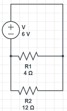
#Purely in-parallel: | #Purely in-parallel: | ||
[[File:Purely_in_parallel.png|220px]] | |||
'''Solution''' | |||
Loop Rule: <math> \Delta V = 0 </math> | |||
Node Rule (designate the current going through <math>R_{1}</math> is <math>I_{1}</math>and the current going through <math>R_{2}</math> is <math>I_{2}</math>, while the total current is <math>I</math> | |||
<math> I_{1} + I_{2}= I </math> | |||
<math> 0 = \varepsilon - I_{1} R_{1} - I_{2} R_{2}</math> | |||
This can also be written in terms of the resistors, where <math> V= I R_{eq} </math> | |||
Because the resistors are in parallel, <math> {\frac{1}{R}_{total}} = {\frac{1}{R}_{1}} + {\frac{1}{R}_{2}} </math> | |||
<math> {\frac{1}{R}_{total}} = {\frac{1}{4}} + {\frac{1}{12}} </math> | |||
<math>R_{total}=3 </math> | |||
<math> 6= I 3 </math> | |||
<math> I=2 </math> | |||
===Middling=== | ===Middling=== | ||
#simple combination of one in-series component or one in-parallel component: | #simple combination of one in-series component or one in-parallel component: | ||
[[File:Series and parallel circuit.PNG|250px]] | |||
We'll start with the most integrated resistors and then work backwards. | |||
First, let's calculate the equivalent resistance of the 4 ohm and 12 ohm resistors in parallel: | |||
<math>{\frac{1}{R}_{total}} = {\frac{1}{R}_{1}} +{\frac{1}{R}_{2}}</math> | |||
<math>{\frac{1}{R}_{total}} = {\frac{1}{4} +{\frac{1}{12}}</math> | |||
[[File: | [[File:Middle_combination.png|frameless|upright=0.7]][http://physicsbook.gatech.edu/File:Middle_combination.PNG] | ||
[[File:1MiddleQuestion.jpg]] | |||
===Difficult=== | ===Difficult=== | ||
#complex combination of in-series and in-parallel components: | #complex combination of in-series and in-parallel components: | ||
[[File:High_combination.png|frameless|upright=0.7]] | |||
[http://physicsbook.gatech.edu/File:High_combination.PNG] | |||
Loop Rule: <math> \Delta V = 0 </math> | |||
Node Rule: <math> I_{2} + I_{3}= I{1} </math> | |||
<math> \Delta V=\varepsilon - I_{1} R_{3} - I_{2} R_{1} - I_{3} R_{2} - I_{3} R_{4} </math> | |||
Substitute <math>I_{1} 0=\varepsilon - (I_{2} + I_{3}) R_{3} - I_{2} R_{1} - I_{3} (R_{2}+R_{4}) </math> | |||
<math>0=\varepsilon - 3(I_{2} + I_{3}) - 4I_{2} - 17I_{3} </math> | |||
<math>0=\varepsilon - 7I_{2} - 20I_{3} </math> | |||
Loop rule for the section with only resistors: <math> 0= -4 I_{2} -17 I_{3} </math> | |||
<math> I_{2}= {\frac{17}{4}} I_{3} </math> | |||
<math> \varepsilon= {\frac{17}{4}}I_{3} + 20 I_{3} </math> | |||
<math> \varepsilon = {\frac{64}{4}} I_{3} </math> | |||
<math> I_{3}= {\frac{24}{63}} </math> | |||
<math> I_{2}= {\frac{17}{4}} I_{3}= {\frac{17}{4}} {\frac{24}{63}} = {\frac{102}{63}} </math> | |||
<math>I_{1}= I_{2} + I_{3}= {\frac{102}{63}}+ {\frac{24}{63}}= {\frac{126}{63}}</math> | |||
==Connectedness== | ==Connectedness== | ||
In complex applications, resistors are combined in both series and parallel to manage the voltage and current in the circuit. When connected in parallel, the current from the power source (usually a battery) is split, increasing the total current. Adding resistors in parallel also decreases the resistance, so to increase resistance, more resistors must be connected in series. | |||
The more complex these circuits, the more difficult it is to locate a problem in a circuit if it arises. Machines, such as airplanes, often have complex wiring and contain many large and complicated electrical circuits. In these non-ideal cases, troubleshooting a short circuit maybe as easy as replacing a burnt out light or separating parts of the circuit in order to try and isolate the problem and locate the source, which maybe faulty wiring or a corroded wire. Corroded wires have a greater resistance than a normal wire, and acts as a resistor connected in series. By measuring the voltage drops, if a faulty wire is creating a great resistance that is dropping large amounts of potential, the other elements of the circuit may not work properly, thus finding the root cause of the issue. | |||
In our daily lives, wall plugs at home are connected in parallel. If they were connected in series, the two plugs on a wall outlet would not share the potential difference (voltage) from the power source equally, so that neither plug gets the full potential difference. | |||
==History== | |||
The fundamental principles of in-series and in-parallel models, ohm's law, an empirical law, was discovered by Georg Ohm, a German scientist, in 1827[https://www.britannica.com/science/Ohms-law], which states "which states that the current flow through a conductor is directly proportional to the potential difference (voltage) and inversely proportional to the resistance." It has many limitations. It can only be applied to ohmic circuits (circuits which only generate heat). Ohm was not recognized for his achievement until 1849, when he finally got the chair in University of Munich. | |||
== | == See also == | ||
===Delta-Wye Circuits=== | |||
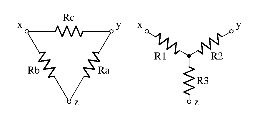
What about the circuits that don't explicitly fit into the category of series or parallel circuits at a first glance? Two examples of these types of circuits are '''delta[Δ]''' and '''wye[Y]''' circuits. These resistor network types are more complicated when attempting to analyze them and the individual resistors within them. You can switch between Δ and Y resistor networks with a couple of mathematical formulas. | |||
[[File:Delta_Y_circuits.png|Delta-Y networks]] | |||
====Delta Circuit==== | |||
This type of circuit is characterized by the formation of a triangle. To find the equivalent Y-circuit for it, you need to employ the following formulas: | |||
<math> R_{1}={\frac{R_{b}*R_{c}}{R_{a}+R_{b}+R_{c}}} </math> | |||
<math> R_{2}={\frac{R_{a}*R_{c}}{R_{a}+R_{b}+R_{c}}} </math> | |||
<math> R_{3}={\frac{R_{a}*R_{b}}{R_{a}+R_{b}+R_{c}}} </math> | |||
To remember this easier, you can notice a pattern forming- the bottom is always a summation of the 3 resistor values and the top is a multiplication of 2 of the resistor values. This way you can find an equivalent resistor to use as a replacement in a Y circuit. | |||
====Wye Circuit==== | |||
This type of circuit is characterized by the formation of a "crossroads". To find the equivalent Δ-circuit for it, you need to employ the following formulas: | |||
<math> R_{a}={\frac{R_{1}*R_{2}+R_{1}*R_{3}+R_{2}*R_{3}}{R_{1}}} </math> | |||
<math> R_{b}={\frac{R_{1}*R_{2}+R_{1}*R_{3}+R_{2}*R_{3}}{R_{2}}} </math> | |||
<math> R_{c}={\frac{R_{1}*R_{2}+R_{1}*R_{3}+R_{2}*R_{3}}{R_{3}}} </math> | |||
To remember this easier, you can notice a pattern forming- the top is always a summation of the multiplication pairs between all 3 resistor values and the bottom is a single resistor we're trying to replace. This way you can find an equivalent resistor to use as a replacement in a Δ circuit. | |||
====Exercises==== | |||
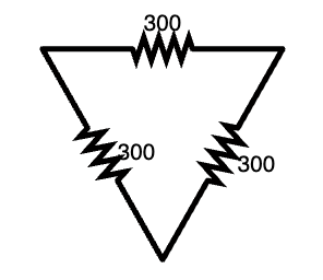
[[File:Delta_network_example.png|Delta network]] | |||
Let's attempt to calculate the equivalent Y network of this Δ configuration. Each resistor in the network is 300Ω. | |||
To start, let's identify each of the resistors in the Δ configuration. | |||
<math> R_{a}=R_{b}=R_{c}=300Ω </math> | |||
Next, we need to calculate the resistances of each of the Y equivalents. Due to the fact that we are using the same value in the Δ configuration, this task will be simple within this example. | |||
<math> R_{1}=R_{2}=R_{3}={\frac{R_{300}*R_{300}}{R_{300}+R_{300}+R_{300}}}=100Ω </math> | |||
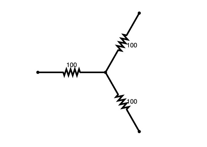
Therefore the equivalent Y circuit would look something like the following diagram: | |||
[[File:Y_network_equivalent.png|Y network equivalent]] | |||
====What is the use of this?==== | |||
The use of this method mainly lies within the ability to simplify larger more complicated networks into more manageable equivalents. As an example, here is a more complex circuit which might benefit from a Δ-Y conversion. | |||
[[File:Complex_delta_Y.png]] | |||
Let's try to calculate the upper delta of this formation. To start, let's define the resistor values at play: | |||
<math> R_{a}=12Ω </math> | |||
<math> R_{b}=18Ω </math> | |||
<math> R_{c}=6Ω </math> | |||
Now let's calculate the resistances needed for the equivalent Y-configuration. | |||
<math> R_{1}={\frac{R_{a}*R_{b}}{R_{a}+R_{b}+R_{c}}}={\frac{12*18}{12+18+6}}=6Ω </math> | |||
<math> R_{2}={\frac{R_{a}*R_{c}}{R_{a}+R_{b}+R_{c}}}={\frac{12*6}{12+18+6}}=2Ω </math> | |||
<math> R_{3}={\frac{R_{b}*R_{c}}{R_{a}+R_{b}+R_{c}}}={\frac{18*6}{12+18+6}}=3Ω </math> | |||
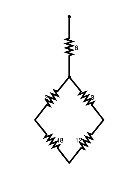
These calculations presented in a Y configuration diagram would look like this- | |||
[[File:Simplified_Delta_Y.png]] | |||
===Further reading=== | ===Further reading and external links=== | ||
Books, Articles or other print media on this topic | Books, Articles or other print media on this topic | ||
| Line 95: | Line 265: | ||
About Ohm's law: | About Ohm's law: | ||
[https://www.britannica.com/science/Ohms-law] | [https://www.britannica.com/science/Ohms-law] | ||
==References== | ==References== | ||
| Line 105: | Line 271: | ||
[[Category:Which Category did you place this in?]] | [[Category:Which Category did you place this in?]] | ||
Georg Ohm[[1]] | Georg Ohm: [[1]] | ||
Latest revision as of 21:24, 16 April 2023
Claimed by Christina Zhao Fall 2018
Edited by Ivan Peshev Spring 2023
The Main Idea
A typical circuit consists of a power source, usually a battery, and electrical elements such as resistors and capacitors. Resistors include light bulbs and do not provide power. Resistors, depending on how they are positioned in a circuit, reduces the voltage or the current that passes through them, and can change the equivalent, or total resistance in a circuit.
Resistors connected in series are attached to the power source in a way that there are no nodes where the current splits. Therefore, according to the node rule, the current flowing through each resistor is the same. However, the voltage drop across each resistor is not equal for every resistor. If these resistors are light bulbs, they are connected in line with the battery. The relative brightness decreases across each bulb, making series connections not ideal for something such as house wiring. This drop is consistent with the loop rule, which states that around a full loop of a circuit, the potential difference is 0.
Resistors connected in parallel are connected to a power source but are on different branches of wire, meaning that the resistors experience the same potential difference. But, due to being connected to different nodes of the circuit, have different currents flowing across them. The branches of a basic parallel circuit looks like rungs of a ladder. If these resistors are light bulbs, they are connected from a common point to the potential of the battery and all have the same brightness.
A Mathematical Model
An ohmic circuit is a set of resistors linked together in an unique combination. It can also include components such as bulbs, heaters, and meters as long as they can be considered ohmic. As is expected, if all the components obey Ohm's Law V=IR, then it is considered ohmic. Such a circuit is easy to analyze when components are connected in parallel or in series by using Ohm's law. We may need to use other laws when analyzing non-ohmic circuits. Any resistors may become non-ohmic under very high voltage, and some may be so under low voltage.
For a purely in-series circuit, (or purely in-series combination of resistors)
[math]\displaystyle{ U_{total}=U_{1}+U_{2}+U_{3}+...+U_{n} }[/math]
[math]\displaystyle{ I_{total}=I_{1}=I_{2}=I_{3}=...=I_{n} }[/math]
[math]\displaystyle{ R_{total} = R_{1} + R_{2} + R_{3} + ... + R_{n} }[/math]
if there are n ohmic components in the circuit connected in series.
For a purely in-parallel circuit, (or purely in-parallel combination of resistors)
[math]\displaystyle{ U_{total} = U_{1} = U_{2} = U_{3} = ... = U_{n} }[/math]
[math]\displaystyle{ I_{total} = I_{1} + I_{2} + I_{3} + ... + I_{n} }[/math]
[math]\displaystyle{ {\frac{1}{R}_{total}} = {\frac{1}{R}_{1}} +{\frac{1}{R}_{2}} + {\frac{1}{R}_{3}} + ... + {\frac{1}{R}_{n}} }[/math]
When a circuit is analyzed, cut up circuits into purely in-series combination of components or purely in-parallel combination of components, calculate resistance of each combination of components. Reduce the circuit until it is purely in-series or in-parallel and calculate the current, total resistance and potential difference between two ends of each component.
A Computational Model
This website is a schematic builder that can be used to model circuits and test differences in current, voltage, and resistance with with various combinations of parallel and series.
Parallel Circuit
This shows an example of a simple circuit consisting of a battery and two lightbulbs wired in parallel. You will notice that both of the bulbs are bright because the same voltage is going across each of them. Brightness is proportional to voltage, a higher voltage produces a brighter light. In this circuit, the lightbulbs are equivalent to resistors. They have current running through them equal to half the total current and all of the voltage the battery puts out.
Series Circuit
This shows an example of a simple circuit consisting of a battery and two lightbulbs wired in series. You will notice that both of the bulbs are dim because half of the total voltage is going across each of them. Brightness is proportional to voltage, a higher voltage produces a brighter light. So, the brightness of the first example can not be achieved by this second circuit. In this circuit the lightbulbs are equivalent to a resistor. They have the same amount of current running through each of them.
How do I remember this?
In order to tell the difference between parallel and series circuits, I like to think of current as being equivalent to water running through pipes. In a straight line, the same amount of water passes through every part of the pipe. Current behaves the same way. So in series circuit the same current runs through all pieces. However, the parallel circuit is equivalent to a pipe with branches. These branches lead to the current being proportionally split by the size of the branch, just like a circuit in parallel.
Examples
Simple
Question
- Purely in-series:
Solution
Using the loop rule, we know that:
[math]\displaystyle{ \Delta V = 0 }[/math]
[math]\displaystyle{ 0 = \varepsilon - I R_{1} - I R_{2} }[/math]
[math]\displaystyle{ 0= 6 - I (4) - I (12) }[/math]
[math]\displaystyle{ 6= 16 I }[/math]
[math]\displaystyle{ I= .375 A }[/math]
Question
- Purely in-parallel:
Solution
Loop Rule: [math]\displaystyle{ \Delta V = 0 }[/math]
Node Rule (designate the current going through [math]\displaystyle{ R_{1} }[/math] is [math]\displaystyle{ I_{1} }[/math]and the current going through [math]\displaystyle{ R_{2} }[/math] is [math]\displaystyle{ I_{2} }[/math], while the total current is [math]\displaystyle{ I }[/math]
[math]\displaystyle{ I_{1} + I_{2}= I }[/math]
[math]\displaystyle{ 0 = \varepsilon - I_{1} R_{1} - I_{2} R_{2} }[/math]
This can also be written in terms of the resistors, where [math]\displaystyle{ V= I R_{eq} }[/math] Because the resistors are in parallel, [math]\displaystyle{ {\frac{1}{R}_{total}} = {\frac{1}{R}_{1}} + {\frac{1}{R}_{2}} }[/math]
[math]\displaystyle{ {\frac{1}{R}_{total}} = {\frac{1}{4}} + {\frac{1}{12}} }[/math]
[math]\displaystyle{ R_{total}=3 }[/math]
[math]\displaystyle{ 6= I 3 }[/math]
[math]\displaystyle{ I=2 }[/math]
Middling
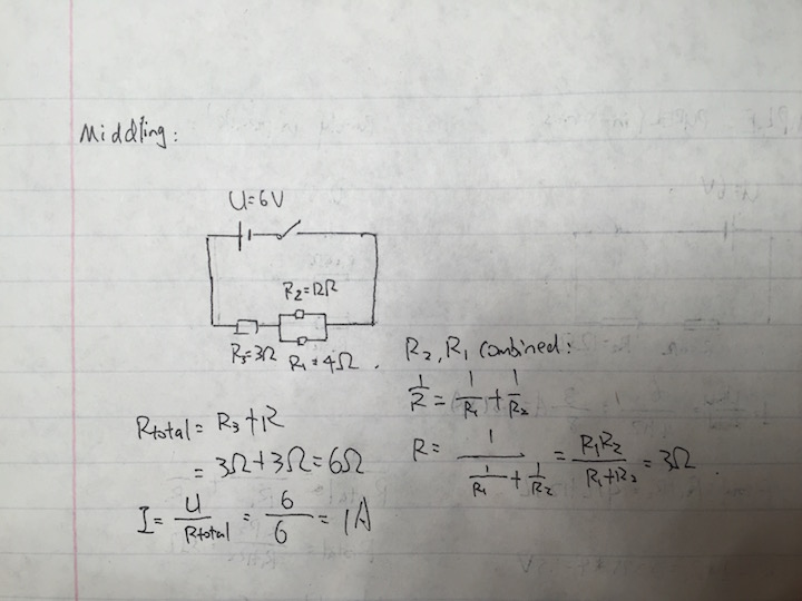
- simple combination of one in-series component or one in-parallel component:
We'll start with the most integrated resistors and then work backwards.
First, let's calculate the equivalent resistance of the 4 ohm and 12 ohm resistors in parallel:
[math]\displaystyle{ {\frac{1}{R}_{total}} = {\frac{1}{R}_{1}} +{\frac{1}{R}_{2}} }[/math]
[math]\displaystyle{ {\frac{1}{R}_{total}} = {\frac{1}{4} +{\frac{1}{12}} }[/math]
File:Middle combination.png[1]
Difficult
- complex combination of in-series and in-parallel components:
Loop Rule: [math]\displaystyle{ \Delta V = 0 }[/math]
Node Rule: [math]\displaystyle{ I_{2} + I_{3}= I{1} }[/math]
[math]\displaystyle{ \Delta V=\varepsilon - I_{1} R_{3} - I_{2} R_{1} - I_{3} R_{2} - I_{3} R_{4} }[/math]
Substitute [math]\displaystyle{ I_{1} 0=\varepsilon - (I_{2} + I_{3}) R_{3} - I_{2} R_{1} - I_{3} (R_{2}+R_{4}) }[/math]
[math]\displaystyle{ 0=\varepsilon - 3(I_{2} + I_{3}) - 4I_{2} - 17I_{3} }[/math]
[math]\displaystyle{ 0=\varepsilon - 7I_{2} - 20I_{3} }[/math]
Loop rule for the section with only resistors: [math]\displaystyle{ 0= -4 I_{2} -17 I_{3} }[/math]
[math]\displaystyle{ I_{2}= {\frac{17}{4}} I_{3} }[/math]
[math]\displaystyle{ \varepsilon= {\frac{17}{4}}I_{3} + 20 I_{3} }[/math]
[math]\displaystyle{ \varepsilon = {\frac{64}{4}} I_{3} }[/math]
[math]\displaystyle{ I_{3}= {\frac{24}{63}} }[/math]
[math]\displaystyle{ I_{2}= {\frac{17}{4}} I_{3}= {\frac{17}{4}} {\frac{24}{63}} = {\frac{102}{63}} }[/math]
[math]\displaystyle{ I_{1}= I_{2} + I_{3}= {\frac{102}{63}}+ {\frac{24}{63}}= {\frac{126}{63}} }[/math]
Connectedness
In complex applications, resistors are combined in both series and parallel to manage the voltage and current in the circuit. When connected in parallel, the current from the power source (usually a battery) is split, increasing the total current. Adding resistors in parallel also decreases the resistance, so to increase resistance, more resistors must be connected in series.
The more complex these circuits, the more difficult it is to locate a problem in a circuit if it arises. Machines, such as airplanes, often have complex wiring and contain many large and complicated electrical circuits. In these non-ideal cases, troubleshooting a short circuit maybe as easy as replacing a burnt out light or separating parts of the circuit in order to try and isolate the problem and locate the source, which maybe faulty wiring or a corroded wire. Corroded wires have a greater resistance than a normal wire, and acts as a resistor connected in series. By measuring the voltage drops, if a faulty wire is creating a great resistance that is dropping large amounts of potential, the other elements of the circuit may not work properly, thus finding the root cause of the issue.
In our daily lives, wall plugs at home are connected in parallel. If they were connected in series, the two plugs on a wall outlet would not share the potential difference (voltage) from the power source equally, so that neither plug gets the full potential difference.
History
The fundamental principles of in-series and in-parallel models, ohm's law, an empirical law, was discovered by Georg Ohm, a German scientist, in 1827[3], which states "which states that the current flow through a conductor is directly proportional to the potential difference (voltage) and inversely proportional to the resistance." It has many limitations. It can only be applied to ohmic circuits (circuits which only generate heat). Ohm was not recognized for his achievement until 1849, when he finally got the chair in University of Munich.
See also
Delta-Wye Circuits
What about the circuits that don't explicitly fit into the category of series or parallel circuits at a first glance? Two examples of these types of circuits are delta[Δ] and wye[Y] circuits. These resistor network types are more complicated when attempting to analyze them and the individual resistors within them. You can switch between Δ and Y resistor networks with a couple of mathematical formulas.
Delta Circuit
This type of circuit is characterized by the formation of a triangle. To find the equivalent Y-circuit for it, you need to employ the following formulas:
[math]\displaystyle{ R_{1}={\frac{R_{b}*R_{c}}{R_{a}+R_{b}+R_{c}}} }[/math]
[math]\displaystyle{ R_{2}={\frac{R_{a}*R_{c}}{R_{a}+R_{b}+R_{c}}} }[/math]
[math]\displaystyle{ R_{3}={\frac{R_{a}*R_{b}}{R_{a}+R_{b}+R_{c}}} }[/math]
To remember this easier, you can notice a pattern forming- the bottom is always a summation of the 3 resistor values and the top is a multiplication of 2 of the resistor values. This way you can find an equivalent resistor to use as a replacement in a Y circuit.
Wye Circuit
This type of circuit is characterized by the formation of a "crossroads". To find the equivalent Δ-circuit for it, you need to employ the following formulas:
[math]\displaystyle{ R_{a}={\frac{R_{1}*R_{2}+R_{1}*R_{3}+R_{2}*R_{3}}{R_{1}}} }[/math]
[math]\displaystyle{ R_{b}={\frac{R_{1}*R_{2}+R_{1}*R_{3}+R_{2}*R_{3}}{R_{2}}} }[/math]
[math]\displaystyle{ R_{c}={\frac{R_{1}*R_{2}+R_{1}*R_{3}+R_{2}*R_{3}}{R_{3}}} }[/math]
To remember this easier, you can notice a pattern forming- the top is always a summation of the multiplication pairs between all 3 resistor values and the bottom is a single resistor we're trying to replace. This way you can find an equivalent resistor to use as a replacement in a Δ circuit.
Exercises
Let's attempt to calculate the equivalent Y network of this Δ configuration. Each resistor in the network is 300Ω.
To start, let's identify each of the resistors in the Δ configuration.
[math]\displaystyle{ R_{a}=R_{b}=R_{c}=300Ω }[/math]
Next, we need to calculate the resistances of each of the Y equivalents. Due to the fact that we are using the same value in the Δ configuration, this task will be simple within this example.
[math]\displaystyle{ R_{1}=R_{2}=R_{3}={\frac{R_{300}*R_{300}}{R_{300}+R_{300}+R_{300}}}=100Ω }[/math]
Therefore the equivalent Y circuit would look something like the following diagram:
What is the use of this?
The use of this method mainly lies within the ability to simplify larger more complicated networks into more manageable equivalents. As an example, here is a more complex circuit which might benefit from a Δ-Y conversion.
Let's try to calculate the upper delta of this formation. To start, let's define the resistor values at play:
[math]\displaystyle{ R_{a}=12Ω }[/math]
[math]\displaystyle{ R_{b}=18Ω }[/math]
[math]\displaystyle{ R_{c}=6Ω }[/math]
Now let's calculate the resistances needed for the equivalent Y-configuration.
[math]\displaystyle{ R_{1}={\frac{R_{a}*R_{b}}{R_{a}+R_{b}+R_{c}}}={\frac{12*18}{12+18+6}}=6Ω }[/math]
[math]\displaystyle{ R_{2}={\frac{R_{a}*R_{c}}{R_{a}+R_{b}+R_{c}}}={\frac{12*6}{12+18+6}}=2Ω }[/math]
[math]\displaystyle{ R_{3}={\frac{R_{b}*R_{c}}{R_{a}+R_{b}+R_{c}}}={\frac{18*6}{12+18+6}}=3Ω }[/math]
These calculations presented in a Y configuration diagram would look like this-
Further reading and external links
Books, Articles or other print media on this topic
About Ohm's law: [6]
References
Georg Ohm: 1


