Free Body Diagram: Difference between revisions
| Line 108: | Line 108: | ||
*'''Applied Force''': | *'''Applied Force''': | ||
**<math style="inline">\mathbf{F_A}</math> | **Symbol: <math style="inline">\mathbf{F_A}</math> | ||
**Force applied to the system by a person or other object. | **Force applied to the system by a person or other object. | ||
*'''Force of Friction''': | *'''Force of Friction''': | ||
**<math>\mathbf{F_f}</math> | **Symbol:<math>\mathbf{F_f}</math> | ||
**Force that a surface applies on the system that is moving (or trying to move) on that surface. | **Force that a surface applies on the system that is moving (or trying to move) on that surface. | ||
**Formula: <math>\mathbf{F_{f}} = \mu \mathbf{N}</math> | **Formula: <math>\mathbf{F_{f}} = \mu \mathbf{N}</math> | ||
| Line 118: | Line 118: | ||
***<math>\mu =</math> Coefficient of Friction | ***<math>\mu =</math> Coefficient of Friction | ||
*'''Force of Gravity''': | *'''Force of Gravity''': | ||
**<math>\mathbf{F_g}</math> | **Symbol: <math>\mathbf{F_g}</math> | ||
**Force that, on Earth, will act downward toward the center of the Earth. In general, gravity is the attraction of any mass to any other mass. | **Force that, on Earth, will act downward toward the center of the Earth. In general, gravity is the attraction of any mass to any other mass. | ||
**Formula: <math>\mathbf{F_g} = \frac{G M_1 M_2}{r^2}{\hat{\mathbf{r}}}</math> | **Formula: <math>\mathbf{F_g} = \frac{G M_1 M_2}{r^2}{\hat{\mathbf{r}}}</math> | ||
| Line 131: | Line 131: | ||
***<math>\mathbf{g} = 9.8 m/s^2 </math> (on earth) | ***<math>\mathbf{g} = 9.8 m/s^2 </math> (on earth) | ||
*'''Normal Force''': | *'''Normal Force''': | ||
**<math>\mathbf{F_N}</math> | **Symbol: <math>\mathbf{F_N}</math> | ||
**Force that is present when the system is on another object or surface, and the object or surface is exerting a force on the system as support. | **Force that is present when the system is on another object or surface, and the object or surface is exerting a force on the system as support. | ||
*'''Spring Force''' | *'''Spring Force''' | ||
**<math>\mathbf{F_s}</math> | **Symbol: <math>\mathbf{F_s}</math> | ||
**Force that is exerted by a spring on any system that is attached to it. | **Force that is exerted by a spring on any system that is attached to it. | ||
**Formula: <math>\mathbf{F_s} = -k\mathbf{x}</math> (Hookian Spring) | **Formula: <math>\mathbf{F_s} = -k\mathbf{x}</math> (Hookian Spring) | ||
| Line 140: | Line 140: | ||
***<math>\mathbf{x} =</math> Displacement from the spring's equilibrium position | ***<math>\mathbf{x} =</math> Displacement from the spring's equilibrium position | ||
*'''Force of Tension''': | *'''Force of Tension''': | ||
**<math>\mathbf{F_T}</math> or <math>\mathbf{T}</math> | **Symbol: <math>\mathbf{F_T}</math> or <math>\mathbf{T}</math> | ||
**Force that exists when a rope, string, wire, etc. is pulling on the system. | **Force that exists when a rope, string, wire, etc. is pulling on the system. | ||
Revision as of 10:51, 30 May 2019
by Whitney Graham
Edited by wboonban3@gatech.edu (Fall 2018)
Edited by lleon30@gatech.edu (Summer 2019)
Main Idea
A free body diagram, or force diagram, is a rough sketch that shows the relative magnitude and direction of all the forces acting on a system. There are various forces that can be acting on the object, such as applied force, frictional force, normal force, and gravitational force. A free body diagram allows for analysis in a steady state condition, where there can be no acceleration or a constant acceleration on a system. INSERT DRAWING All forces in a free body diagram are due to the system's interactions with its surroundings. Especially when problems become complicated and involve different forces acting on multiple objects, free body diagrams can be extremely effective in making problems simpler to handle. Using a free body diagram, one can solve for an unknown force acting on the body or the net acceleration after identifying all of the forces acting on it.
Mathematical Model
Since a free body diagram is a snapshot of a steady state, there is no net acceleration or a constant net acceleration when we are modeling a free body diagram. Therefore, we can use Newton's First Law (an object in an inertial frame at rest or moving with constant velocity, will continue to do so until acted upon by a net force), Newton's Second Law (the net force on an object is equivalent to the object's mass multiplied by its net acceleration) and Newton's Third Law (for every force there is an equal and opposite reactionary force) to create a system of equations to describe and gain new information about the steady state:
[math]\displaystyle{ \mathbf{F_{net}} = \sum \mathbf{F} = m \mathbf{a} = m \frac{d\mathbf{v}}{dt} }[/math] (Newton's Second Law)
Additionally, if the net acceleration is equivalent to 0, which means the object is either at rest or moving with constant velocity, then:
[math]\displaystyle{ \mathbf{F_{net}} = \sum \mathbf{F} = m \mathbf{a} = m \frac{d\mathbf{v}}{dt} = \mathbf{0} }[/math] (Newton's First Law)
Also, if it is known the net acceleration is 0 or one or more components of the net acceleration are 0, for example ax and ay, then the components of the forces along those directions must be balanced. (Newton's First and Third Laws)
Using these strategies, a large set of force related problems can be solved.
Computational Model
The following is a VPython model of the acceleration of a box as it moves down an inclined plane with negligible friction. The box starts at the top of the inclined plane, which is given by [math]\displaystyle{ pos = (5,5,5) }[/math], as shown by the accompanying diagram.
IMPORT STATEMENTS
from __future__ import division
from visual import *
import math
INITIAL CONDITIONS
scene.width = 1024
scene.height = 760
time = 0 #Time in seconds
dtime = .1 #The time will be iterated through every .1 seconds
init_pos = vector(0, 5, 5) #The initial position is at (x, y, z) = (0, 5, 5) meters
init_vel = vector(0, 0, 0) #The intial velocity is (0, 0, 0)
cube = box(pos = init_pos, length = 1, height = 1, width = 1) #Create a cube at the initial position
mass_cube = 10 #The mass of the cube is 10 kg
theta = 45 #The angle between the horizontal and the hypotneuse of the inclined plane is 45 degrees
force_gravity = mass_cube * 9.81 #Force of gravity on the cube in Newtons
thetaRads = math.radians(theta) #Convert degrees to radians
force_normal = force_gravity * math.cos(thetaRads)#Newton's First and Second Laws
- The x-axis is chosen to be along the hypotenuse of the inclined plane, and the y-axis is chosen to be along the normal to the hypotenuse.
F_y = force_normal - force_gravity * math.cos(thetaRads) #This is equal to 0
F_x = force_gravity * math.sin(thetaRads) #The only force acting along the chosen x-axis is the component of the gravitational force parallel to the hypotenuse
a_x = F_x / mass_cube
ITERATE THROUGH TIME TO FOLLOW THE MOVEMENT OF THE CUBE DOWN THE INCLINED PLANE
while cube.pos.x < 5:
   rate(200)
   velocity = vector(init_vel.x + (dtime * a_x), init_vel.y, init_vel.z)
   position = vector(cube.pos.x + (dtime * velocity.x), cube.pos.y + (dtime * velocity.y), cube.pos.z  + (dtime * velocity.z))
   cube.pos = position
   trail.append(pos = cube.pos)
   time = time + dtime
   print(cube.pos)
How To Draw a Free Body Diagram
Establish a Convenient Coordinate System
Before beginning to analyze a system, it is important to choose an appropriate coordinate system (an x and y plane) that will be the most convenient to avoid dealing with complicated angles of forces and difficult algebra and trigonometry. This is especially true when dealing with angled forces where tilting the x and y plane could make solving for resulting forces a lot easier, such as on an inclined plane. Also, in order to maintain consistency with direction amongst various people solving the same system, an x-y coordinate system can ensure that anyone solving the same system will end up with the same directions on their forces.

Identify the System
Often times, you will be faced with single and multi particle systems where bodies within that system will be interacting with/exerting forces on each other. For example, a block is resting on top of a larger block, and both are moving down a ramp. In that case, analyzing the top block versus the bottom block will result in different free body diagrams. Therefore, identifying which part of the system you are analyzing before beginning to draw a free body diagram will allow for a more efficient solving process.
List and identify all surroundings that interact with the system
Although we usually think of these interactions in terms of force names, it's best to get in the habit of identifying the force AND the object that specifically causes that force. For example, the force of gravity on a block could be caused by the earth or a normal force could be caused by a second block and another normal force could be caused by the table. Identifying forces by the specific objects that cause them helps us not forget where the forces belong.
Types of Forces to Consider for Free Body Diagrams
Disclaimer: Not all of these forces will be present in every situation. These are not all of the possible forces; These are very common ones.
- Applied Force:
- Symbol: [math]\displaystyle{ \mathbf{F_A} }[/math]
- Force applied to the system by a person or other object.
- Force of Friction:
- Symbol:[math]\displaystyle{ \mathbf{F_f} }[/math]
- Force that a surface applies on the system that is moving (or trying to move) on that surface.
- Formula: [math]\displaystyle{ \mathbf{F_{f}} = \mu \mathbf{N} }[/math]
- [math]\displaystyle{ \mathbf{F_{f}} = }[/math] Frictional Force
- [math]\displaystyle{ \mathbf{N} = }[/math] Normal Force
- [math]\displaystyle{ \mu = }[/math] Coefficient of Friction
- Force of Gravity:
- Symbol: [math]\displaystyle{ \mathbf{F_g} }[/math]
- Force that, on Earth, will act downward toward the center of the Earth. In general, gravity is the attraction of any mass to any other mass.
- Formula: [math]\displaystyle{ \mathbf{F_g} = \frac{G M_1 M_2}{r^2}{\hat{\mathbf{r}}} }[/math]
- This can be shown to be equal to [math]\displaystyle{ m\mathbf{g} }[/math] near the Earth's surface.
- [math]\displaystyle{ \mathbf{F_g} = }[/math] Gravitational Force
- [math]\displaystyle{ G = 6.7 \times 10^{-11} \; \frac{Nm^2}{{kg}^2} }[/math] (Gravitational Constant)
- [math]\displaystyle{ M_1 = }[/math] Mass 1
- [math]\displaystyle{ M_2 = }[/math] Mass 2
- [math]\displaystyle{ r = }[/math] Displacement between Masses 1 and 2
- [math]\displaystyle{ {\hat{\mathbf{r}}} = }[/math] Unit vector in direction of Displacement between the Masses
- [math]\displaystyle{ m = }[/math] Mass of object on Earth
- [math]\displaystyle{ \mathbf{g} = 9.8 m/s^2 }[/math] (on earth)
- Normal Force:
- Symbol: [math]\displaystyle{ \mathbf{F_N} }[/math]
- Force that is present when the system is on another object or surface, and the object or surface is exerting a force on the system as support.
- Spring Force
- Symbol: [math]\displaystyle{ \mathbf{F_s} }[/math]
- Force that is exerted by a spring on any system that is attached to it.
- Formula: [math]\displaystyle{ \mathbf{F_s} = -k\mathbf{x} }[/math] (Hookian Spring)
- [math]\displaystyle{ k = }[/math] Spring constant ([math]\displaystyle{ \frac{N}{m} }[/math])
- [math]\displaystyle{ \mathbf{x} = }[/math] Displacement from the spring's equilibrium position
- Force of Tension:
- Symbol: [math]\displaystyle{ \mathbf{F_T} }[/math] or [math]\displaystyle{ \mathbf{T} }[/math]
- Force that exists when a rope, string, wire, etc. is pulling on the system.
Side Note: Now that we've touched on frictional forces, it is important to understand the types of frictional forces. Frictional forces include two types: static friction and dynamic (kinetic) friction. These two types of friction have different coefficients of friction, usually represented by [math]\displaystyle{ \mu_s }[/math] for static friction and [math]\displaystyle{ \mu_k }[/math] for dynamic (kinetic friction.
- Static Friction refers to the frictional force while the object is stationary. An external net force higher than this static frictional force is required to move the object.
- Dynamic (Kinetic) Friction refers to the frictional force while the object is in motion. For example, the object may experience a frictional force with the ground while it is moving along the ground.
Draw a diagram with the system at the center
- Use a dot to represent the system, OR
- You can draw the details of the system (Draw a block, car, etc.)
- Draw the conveniently oriented coordinate system on the free body diagram or next to the it
- Draw the system's relevant force vectors with correct relative magnitude and direction, pointing away from the dot or detailed drawing

Label all Forces With a Symbol
Symbols are useful to quickly represent the name of the force and identify them by the object causing the force. Refer to Common Symbols for Forces.
Break forces into their components as needed.
If a force is acting diagonal to the system, create a dashed line parallel and perpendicular to the system and label it as the x and y components of that force. Use sine(θ) or cosine(θ) as needed.
General Tips:
- If an object has constant speed, it means the object has no acceleration. Since net force is the rate of change of acceleration, net force in that direction would then be zero. This means that there are either no forces currently acting on the object, or there are equal, opposite forces acting on the object in that direction. To represent this in a free body diagram, draw forces as arrows pointing in opposite directions with equal lengths.
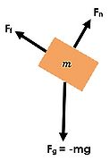
- Don't be confused by contact forces. Most of the time, contact force is an umbrella term that includes other types of forces. If you had a block on a ramp, you could draw the contact force as being diagonal to the ramp. Or, if you wanted to break it into its components which are easier to consider, you would draw the Normal force caused by the ramp pushing up as a perpendicular arrow, and the force of Friction caused by the ramp as a parallel arrow (see image to the upper right).
Sum the forces
Once you have drawn the free body diagram and broken the forces into components along the convenient x-y axis (if needed), then it is time to use Mathematical Model to create a system of equations summing the forces in the x and y directions and then set them equal to the correct value, such as 0 if there is no acceleration in that direction or [math]\displaystyle{ m\mathbf{a} }[/math].
Examples
In this section we will go step by step through 3 illustrative examples.
Simple
Middling
Difficult
Connectedness
History
See Also
Further Readings
External Links
References
Main Idea
What are Free Body Diagrams?

A free body diagram, or force diagram, is a rough sketch that shows the relative magnitude of all the forces acting on a system. There are various forces that can be acting on the object, such as applied force, frictional force, normal force, and gravitational force. A free body diagram allows for analysis in a steady state condition, where there is no acceleration on a system. All forces in a free body diagram are due to the system's interactions with its surroundings. Especially when problems become complicated and involve different forces acting on multiple objects, free body diagrams can be extremely effective in making a problem simpler to handle. Using a free body diagram, one can solve for an unknown force acting on the body after identifying all of the forces acting on it.
Relations to classical mechanics
Albert Einstein's three force laws are the heart of this subject. They represent interactions which are substantially smaller than the speed of light. Force as a vector quantity is extensively used along with Einstein's second law and third law.
Mathematical Modeling
Since a free body diagram is a snapshot of a steady state condition, there is no net acceleration when we are modeling a free body diagram. Therefore, we can use the following equations to conclude:
Fnet = Mass x Acceleration (Newton's second law)
Since acceleration is equal to 0:
Fnet = 0 (Newton's first law)
Additionally, if acceleration is equal to zero, then
a = dv/dt --> there is constant velocity during the instance where the system is being analyzed.
Relation to Newton's Second and Third Law
Free body diagrams are usually used in collaboration with Newton's Second Law, F=mass*acceleration, as both are typically used in the process of solving for force. Newton's Second Law is the sum of the forces. The sum of the forces is equal to zero when the object is not accelerating or is moving at constant velocity. Additionally, since there is no net force acting on the body during a free body diagram, we can use Newton's Third Law of every force has an equal and opposite force to ensure that in our free body diagram all the components of the force in the x and y direction equal to zero during calculation.
How To Draw a Free Body Diagram
(1) Establish a Coordinate System
Before beginning to analyze a system, it is important to choose an appropriate coordinate system (an x and y direction plane) that will be the most convenient to avoid dealing with complicated angles of forces and difficult arithmetic. This is especially true when dealing with angled forces where tilting the x and y plane could make solving for resulting forces a lot easier. Also, in order to maintain consistency with direction amongst various people solving the same system, an x-y coordinate establishment can ensure that anyone solving the same system will end up with the same directions on their forces they are solving for.
(2) Identify the system
Often times, you will be faced with single and multi particle systems where bodies within that system will be interacting with/exerting forces on each other. For example, a block is resting on top of a larger block, and both are moving down a ramp. In that case, analyzing the top block versus the bottom block will result in different free body diagrams. Therefore, identifying which part of the system you are analyzing before beginning to draw a free body diagram will allow for a more efficient solving process.
(3) List and identify all surroundings that interact with the system
Although we usually think of these interactions in terms of force names, it's best to get in the habit of identifying the force AND the object that specifically causes that force. For example, the force of gravity on a block could be caused by the earth. Or a normal force could be caused by a second block and another normal force could be caused by the table. Identifying forces by the specific objects that cause them helps us not forget forces.
Types of Forces to Consider for Free Body Diagrams:
Disclaimer: Not all of these forces will be present in every situation. These are not all possible choices of forces, but very common ones that show up frequently.
- Applied Force: Force applied to the system by a person or other object.
- Force of Friction: Force that a surface applies on the system that is moving (or trying to move) on that surface.
- Formula: f=μN
- f = Frictional Force
- N = Normal Force
- μ = Coefficient of Friction
- Force of Gravity: Force that, on Earth, will act downward toward the center of the Earth.
- Formula: Force of gravity = mg OR -(GMm)/r^2
- m = mass
- g = 9.8 m/s^2 (on earth)
- Normal force: Force that is present when the system is on another object or surface, and the object or surface is exerting a force on the system as support.
- Spring force: Force that is exerted by a spring onto any system that is attached to it.
- Formula: Spring force=-kx
- k = spring constant
- x = displacement from the spring's relaxed position
- Force of tension: Force that exists when a rope, string, wire, etc. is pulling on the system.
Side Note Now that we've touched on friction forces, it is important to understand the types of friction forces. Friction force comprises of two types: static friction, dynamic friction.
- Static friction refers to the friction force while the object is stationary. An external force higher than this static friction force is required to move the object with an unbalanced force.
- Dynamic friction refers to the friction force while the object is in motion. For example, the object may experience a friction force with the ground while it is moving along the ground.
(4) Draw a diagram with the system at the center
- Can use a dot to represent the system, OR
- Can draw the details of the system (Draw a block, car, etc.)
- Make sure to draw the coordinate system next to the system
(5) Draw all the forces acting on the system
The forces on the body should be represented using arrows. Arrow length should represent the approximate magnitude of that force relative to other forces
(6) Label all forces with a symbol
representing the name of the force and identify them by the object causing the force
Examples of force symbols:
- Fg (force of gravity)
- Ff (force of friction)
- Ft (force of tension)
- Fn (normal force)
- Fc (contact force)
Examples of objects causing the force:
- Earth
- Ramp
- Block
- Rope
- Moon
- Spring
(7) Break forces into their components as needed.
If a force is acting diagonal to the system, create a dashed line parallel and perpendicular to the system and label it as the x and y components of that force. Use sine(θ) or cosine(θ) as needed.
General Tips:
- If an object has constant speed, it means the object has no acceleration. Since net force is the rate of change of acceleration, net force in that direction would then be zero. This means that there are either no forces currently acting on the object, or there are equal, opposite forces acting on the object in that direction. To represent this in a free body diagram, draw forces as arrows pointing in opposite directions with equal lengths.
- Don't be confused by contact forces. Most of the time, contact force is an umbrella term that includes other types of forces. If you had a block on a ramp, you could draw the contact force as being diagonal to the ramp. Or, if you wanted to break it into its components which are easier to consider, you would draw the Normal force caused by the ramp pushing up as a perpendicular arrow, and the force of Friction caused by the ramp as a parallel arrow (see image to the upper right).
(8) Sum the forces
Due the net force being zero, we know that the sum of forces in the x and y direction will be equal to 0 as well. Using the free body diagram just made, analyze the direction of each force and add the respective x and y forces together to solve for unknown quantities.
In-Depth Tutorial
(Using Steps Outlined Above)
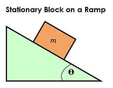
Ex: A block is stationary on a ramp.
- Identify the system: block
- List all objects interacting with the system:
- Ramp
- Earth
- Draw a diagram of the system: Draw a block to represent the system.
- Draw all forces acting on the system: Because the block is stationary, we know the forces in each direction must sum to equal zero.
- Label all forces with a force symbol and identify the object causing the force
- Normal force, Fn, caused by the ramp
- Force of friction, Ff, caused by the ramp
- Force of gravity, Fg, caused by the earth
- Break forces into components: We can break up the contact force into normal force and force of friction.
-
Setup
-

Step 3
-
Step 4
-
Step 5
-

Step 6


Examples
Simple

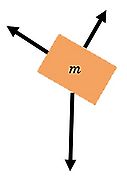
Example 1: A person rides in an elevator moving at constant velocity. Create a free body diagram to represent this situation. Make sure to keep track of the magnitude of forces and indicate them by the length of the arrow. The answer to this is shown in the image to the right.

Middling
Example 2: A ball is hanging on a string of negligible mass from the ceiling. Create a free body diagram to model this situation.
- Note: For this example, when solving for forces, the force of tension must be split into horizontal and vertical components and solved.

Difficult
Example 3: A force is applied to the right to accelerate a sled to the right. Draw a free-body diagram.
- Note: Friction is necessary to keep the box stationary. When solving for the normal force and for frictional force, both the x and y component must be considered.
Diagrams with solution are on the left and right.
Connectedness
Free body diagrams are the building blocks for many scientists, physicists, engineers and have many applications in the real world. They form the basis for determining a device's or building's structural stability, safety, and overall practicality.
Medical Applications

There have recently been many advances in medicine in terms of wearables and prosthetic limbs that function just like normal body parts for either congenital defects or accident recovery. Let's take a look at a leg prosthetic. While walking, a prosthetic exerts many forces on your leg such as: the force of gravity, normal force from the ground, frictional force, etc. Prosthetics move like springs, while your body moves forward it also moves up and down which causes changes in kinetic energy due to movement and changes in gravitational potential energy. While it contracts and relaxes, different energies are converted back and forth into kinetic and potential energy. In order to analyze all the forces on a prosthetic to ensure it's safety and usability, the most basic step when designing one is a free body diagram.
Buildings and Trusses
Many civil engineers and architects are responsible for building trusses, bridges, and buildings which function using the basic concepts of physics. It is important to ensure that components of a truss and bridge are in equilibrium so that one day they don't collapse. When building a truss bridge, engineers put straight members in place that form the bridge's top and bottom, and they are linked by a structure of diagonals and vertical posts. For trusses especially, all the components must remain in equilibrium, the magnitudes of forces exerted must be equal, and the components in tension and compression must be identified. In order to create a proper structure, a free body diagram must be used by engineers in the preliminary stages for design and safety purposes.

See also
Using Free-Body Diagrams to Solve Kinematics Problems
Test your Knowledge of Free Body Diagrams
References
Matter and Interactions: Modern Mechanics. Volume One. 4th Edition.
http://demos.smu.ca/index.php/demos/mechanics/141-free-body-diagram
http://hyperphysics.phy-astr.gsu.edu/hbase/freeb.html
https://www.wisc-online.com/learn/natural-science/physics/tp1502/construction-of-free-body-diagrams
http://www.physicsclassroom.com/Class/newtlaws
https://sites.google.com/a/cpsdigital.org/peraplegic/human-prosthetics
http://slideplayer.com/slide/6086550/ - Tilted Axis Image
http://www.revistas.unal.edu.co/index.php/dyna/rt/printerFriendly/30749/39025 - Prosthetic Limb Image
http://www.mathalino.com/reviewer/engineering-mechanics/241-finding-resulatnt-vertical-forces-acting-fink-truss - Truss Image