Current in an LC Circuit: Difference between revisions
No edit summary |
|||
| Line 24: | Line 24: | ||
Therefore, the current is given by: <math> I = -\frac{dQ}{dt} = \frac{Q_{i}}{\sqrt{LC}}sin(\frac{1}{\sqrt{LC}}t) </math> | Therefore, the current is given by: <math> I = -\frac{dQ}{dt} = \frac{Q_{i}}{\sqrt{LC}}sin(\frac{1}{\sqrt{LC}}t) </math> | ||
===A Computational Model=== | |||
[[File:LCcircuit.jpg]] | |||
How do we visualize or predict using this topic. Consider embedding some vpython code here [https://trinket.io/glowscript/31d0f9ad9e Teach hands-on with GlowScript] | |||
==Examples== | |||
Be sure to show all steps in your solution and include diagrams whenever possible | |||
===Simple=== | |||
===Middling=== | |||
===Difficult=== | |||
==Connectedness== | |||
#How is this topic connected to something that you are interested in? | |||
#How is it connected to your major? | |||
#Is there an interesting industrial application? | |||
==History== | |||
Put this idea in historical context. Give the reader the Who, What, When, Where, and Why. | |||
== See also == | |||
Are there related topics or categories in this wiki resource for the curious reader to explore? How does this topic fit into that context? | |||
===Further reading=== | |||
Books, Articles or other print media on this topic | |||
===External links=== | |||
Internet resources on this topic | |||
==References== | |||
This section contains the the references you used while writing this page | |||
[[Category:Which Category did you place this in?]] | |||
Revision as of 00:31, 6 December 2015
CLAIMED BY: Kelsey Dobson 12/5/2015
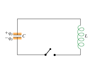
An LC circuit contains an inductor and a capacitor, and because of the inductor's sluggishness and resistance to change the current, the charge in this circuit can oscillate back and forth forever.
The Main Idea
A circuit containing an inductor "L" and a capacitor "C" is called an LC circuit. This circuit can oscillate continuously if the resistance is small. Accordingly, the connecting wires in an LC circuit are low-resistance thick copper wires. Here is the basic idea behind the process of an LC circuit:
A capacitor is charged initially, and then a switch is closed. This connects the capacitor to the inductor. At first, because of the nature of an inductor, it is difficult for charge on the capacitor to flow through the inductor. This is because the inductor opposes all attempts to change the current. However, since an inductor cannot completely prevent a current from changing, there is more current little by little. This drains the capacitor of its charge.
At the moment the capacitor runs out of charge, there is a current in the inductor, and because inductors are sluggish by nature, the current can't immediately change to zero. Therefore, the system does not come to equililbrium and instead increases the charge in the capacitor. When the capacitor is fully charged, it starts to discharge back through the inductor, and the process repeats. Since the circuit will never reach equilibrium and current never reaches zero, this oscillating process repeats forever. Oscillations could reach a stopping point if there is some resistance, but it may still go through multiple cycles before equilibrium is reached.
A Mathematical Model
An LC circuit has an energy conservation rule associated with it. The energy conservation loop rule for an LC circuit is: [math]\displaystyle{ \Delta V_{capacitor} + \Delta V_{inductor} = \frac{1}{C}-L\frac{dI}{dt} = 0 }[/math] where [math]\displaystyle{ Q }[/math] is the charge on the upper plate of the capacitor and [math]\displaystyle{ I }[/math] is the conventional current leaving the upper plate and going through the inductor.
[math]\displaystyle{ dQ/dt }[/math] is the amount of charge flowing off the capacitor every second. This is the same as the current. Because the charge is leaving the capacitor, [math]\displaystyle{ I = -\frac{dQ}{dt} }[/math].
Energy conservation can be re-written as [math]\displaystyle{ \frac{1}{C}Q+L\frac{d^{2}Q}{dt^{2}} = 0 }[/math]
In addition, by substituting Q and its second derivative into the equation, a possible solution of the rewritten energy conservation equation is [math]\displaystyle{ Q = Q_{i}cos(\frac{1}{\sqrt{LC}}t) }[/math]
Therefore, the current is given by: [math]\displaystyle{ I = -\frac{dQ}{dt} = \frac{Q_{i}}{\sqrt{LC}}sin(\frac{1}{\sqrt{LC}}t) }[/math]
A Computational Model
How do we visualize or predict using this topic. Consider embedding some vpython code here Teach hands-on with GlowScript
Examples
Be sure to show all steps in your solution and include diagrams whenever possible
Simple
Middling
Difficult
Connectedness
- How is this topic connected to something that you are interested in?
- How is it connected to your major?
- Is there an interesting industrial application?
History
Put this idea in historical context. Give the reader the Who, What, When, Where, and Why.
See also
Are there related topics or categories in this wiki resource for the curious reader to explore? How does this topic fit into that context?
Further reading
Books, Articles or other print media on this topic
External links
Internet resources on this topic
References
This section contains the the references you used while writing this page
