Free Body Diagram: Difference between revisions
| Line 122: | Line 122: | ||
== Connectedness == | == Connectedness == | ||
While free body diagrams do not necessarily correlate with my life, they do have an application in the real world. For example, companies designing things such as billboards and even things such as houses, free body diagrams can be used to solve for how much force the structure must be supporting before construction begins. | While free body diagrams do not necessarily correlate with my life, they do have an application in the real world. For example, companies designing things such as billboards and even things such as houses, free body diagrams can be used to solve for how much force the structure must be supporting before construction begins. | ||
Revision as of 18:18, 27 November 2016
by Whitney Graham
Edited by pgupta66@gatech.edu (Fall 2016)
Main Idea
What are Free Body Diagrams?

A free body diagram, or force diagram, is a rough sketch that shows the relative magnitude of all the forces acting on a system. There are various forces that can be acting on the object, such as applied force, frictional force, normal force, and gravitational force. A free body diagram allows for analysis in a steady state condition, where there is no acceleration on a system. All forces in a free body diagram are due to the system's interactions with its surroundings. Especially when problems become complicated and involve different forces acting on multiple objects, free body diagrams can be extremely effective in making a problem simpler to handle.
Relation to Newton's Second Law
Free body diagrams are usually used in collaboration with Newton's Second Law, F=mass*acceleration, as both are typically used in the process of solving for force. Newton's Second Law is the sum of the forces. The sum of the forces is equal to zero when the object is not accelerating or is moving at constant velocity.
How To Draw a Free Body Diagram
(1) Establish a Coordinate System
Before beginning to analyze a system, it is important to choose an appropriate coordinate system (an x and y direction plane) that will be the most convenient to avoid dealing with complicated angles of forces and difficult arithmetic. This is especially true when dealing with angled forces where tilting the x and y plane could make solving for resulting forces a lot easier. Also, in order to maintain consistency with direction amongst various people solving the same system, an x-y coordinate establishment can ensure that anyone solving the same system will end up with the same directions on their forces they are solving for.

(2) Identify the system
Often times, you will be faced with single and multi particle systems where bodies within that system will be interacting with/exerting forces on each other. For example, a block is resting on top of a larger block, and both are moving down a ramp. In that case, analyzing the top block versus the bottom block will result in different free body diagrams. Therefore, identifying which part of the system you are analyzing before beginning to draw a free body diagram will allow for a more efficient solving process.
(3) List and identify all surroundings that interact with the system
Although we usually think of these interactions in terms of force names, it's best to get in the habit of identifying the force AND the object that specifically causes that force. For example, the force of gravity on a block could be caused by the earth. Or a normal force could be caused by a second block and another normal force could be caused by the table. Identifying forces by the specific objects that cause them helps us not forget forces.
Types of Forces to Consider for Free Body Diagrams:
Disclaimer: Not all of these forces will be present in every situation. These are not all possible choices of forces, just the most common in a Physics 1 course.
- Applied Force: Force applied to the system by a person or other object.
- Force of Friction: Force that a surface applies on the system that is moving (or trying to move) on that surface.
- Formula: f=μN
- f = Frictional Force
- N = Normal Force
- μ = Coefficient of Friction
- Force of Gravity: Force that, on Earth, will act downward toward the center of the Earth.
- Formula: Force of gravity = mg OR -(GMm)/r^2
- m = mass
- g = 9.8 m/s^2 (on earth)
- Normal force: Force that is present when the system is on another object or surface, and the object or surface is exerting a force on the system as support.
- Spring force: Force that is exerted by a spring onto any system that is attached to it.
- Formula: Spring force=-kx
- k = spring constant
- x = displacement from the spring's relaxed position
- Force of tension: Force that exists when a rope, string, wire, etc. is pulling on the system.
(4) Draw a diagram with the system at the center
- Can use a dot to represent the system, OR
- Can draw the details of the system (Draw a block, car, etc.)
(5) Draw all the forces acting on the system
(represented as arrows). Arrow length should represent the approximate magnitude of that force relative to other forces

(6) Label all forces with a symbol
representing the name of the force and identify them by the object causing the force
Examples of force symbols:
- Fg (force of gravity)
- Ff (force of friction)
- Ft (force of tension)
- Fn (normal force)
- Fc (contact force)
Examples of objects causing the force:
- Earth
- Ramp
- Block
- Rope
- Moon
- Spring
(7) Break forces into their components as needed.
If a force is acting diagonal to the system, create a dashed line parallel and perpendicular to the system and label it as the x and y components of that force. Use sine(θ) or cosine(θ) as needed.
General Tips:
- If an object has constant speed, it means the object has no acceleration. Since net force is the rate of change of acceleration, net force in that direction would then be zero. This means that there are either no forces currently acting on the object, or there are equal, opposite forces acting on the object in that direction. To represent this in a free body diagram, draw forces as arrows pointing in opposite directions with equal lengths.
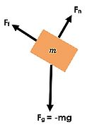
- Don't be confused by contact forces. Most of the time, contact force is an umbrella term that includes other types of forces. If you had a block on a ramp, you could draw the contact force as being diagonal to the ramp. Or, if you wanted to break it into its components which are easier to consider, you would draw the Normal force caused by the ramp pushing up as a perpendicular arrow, and the force of Friction caused by the ramp as a parallel arrow (see image to the upper right).
In-Depth Tutorial
(Using Steps Outlined Above)
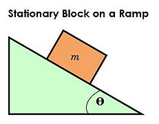
Ex: A block is stationary on a ramp.
- Identify the system: block
- List all objects interacting with the system:
- Ramp
- Earth
- Draw a diagram of the system: Draw a block to represent the system.
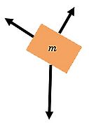
- Draw all forces acting on the system: Because the block is stationary, we know the forces in each direction must sum to equal zero.
- Label all forces with a force symbol and identify the object causing the force
- Normal force, Fn, caused by the ramp
- Force of friction, Ff, caused by the ramp
- Force of gravity, Fg, caused by the earth
- Break forces into components: We can break up the contact force into normal force and force of friction.
-
 Setup
Setup -
 Step 3
 -
 Step 4
 -
 Step 5
 -
 Step 6


Examples
Simple
Example 1: A person rides in an elevator moving at constant velocity. Create a free body diagram to represent this situation.

Middling
Example 2: A ball is hanging on a string of negligible mass from the ceiling. Create a free body diagram to model this situation.

- Note: For this example, when solving for forces, the force of tension must be split into horizontal and vertical components and solved.
Difficult
Example 3: A force is applied to the right to accelerate a sled to the right. Draw a free-body diagram.

- Note: Friction is necessary to keep the box stationary. When solving for the normal force and for frictional force, both the x and y component must be considered.

Diagrams with solution are on the left and right.
Connectedness
While free body diagrams do not necessarily correlate with my life, they do have an application in the real world. For example, companies designing things such as billboards and even things such as houses, free body diagrams can be used to solve for how much force the structure must be supporting before construction begins.
See also
Using Free-Body Diagrams to Solve Kinematics Problems
References
Matter and Interactions: Modern Mechanics. Volume One. 4th Edition.
http://demos.smu.ca/index.php/demos/mechanics/141-free-body-diagram
http://hyperphysics.phy-astr.gsu.edu/hbase/freeb.html
https://www.wisc-online.com/learn/natural-science/physics/tp1502/construction-of-free-body-diagrams